
Transfusion injection device

An injection device and instillation technology, applied in pressure infusion, instruments introduced into the body, etc., can solve problems such as inability of patients to settle in one place or a fixed posture, inconvenience for users, and long use of instillation injections.

Inactive Publication Date: 2006-07-19
杨章民
View PDF0 Cites 4 Cited by
  • Summary
  • Abstract
  • Description
  • Claims
  • Application Information

AI Technical Summary

Problems solved by technology

[0002] At present, the drip injection device on the market uses a bag-shaped or drip bottle injection method. The injection device must hang the drip high to use atmospheric pressure to inject the liquid in the drip along the catheter to the patient. Due to the high-hanging type The injection device is easy to cause blood backflow due to the patient's carelessness
In addition, because the high-hanging injection method is easy to cause inconvenience to the user, in terms of action, the user must rely on the hanger or others to hang the drip high, so that the liquid in the drip will not be interrupted
However, because the drip injection takes a long time to use, it is impossible to stabilize the patient in one place or fix a posture, so that the medical staff must always pay attention to the patient's situation
[0003] It can be seen that the above-mentioned customary method still has many deficiencies, and it is not a good designer, and needs to be improved urgently.

Method used


Image

  • Transfusion injection device
  • Transfusion injection device
  • Transfusion injection device

Examples


Embodiment Construction

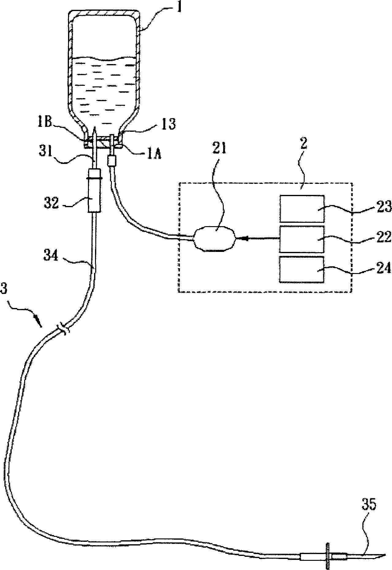
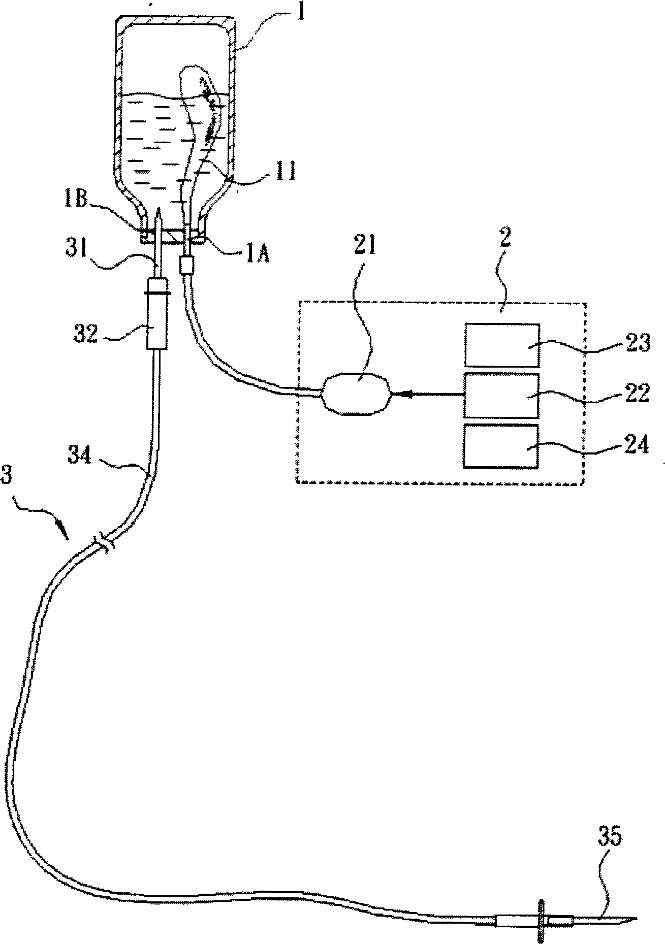
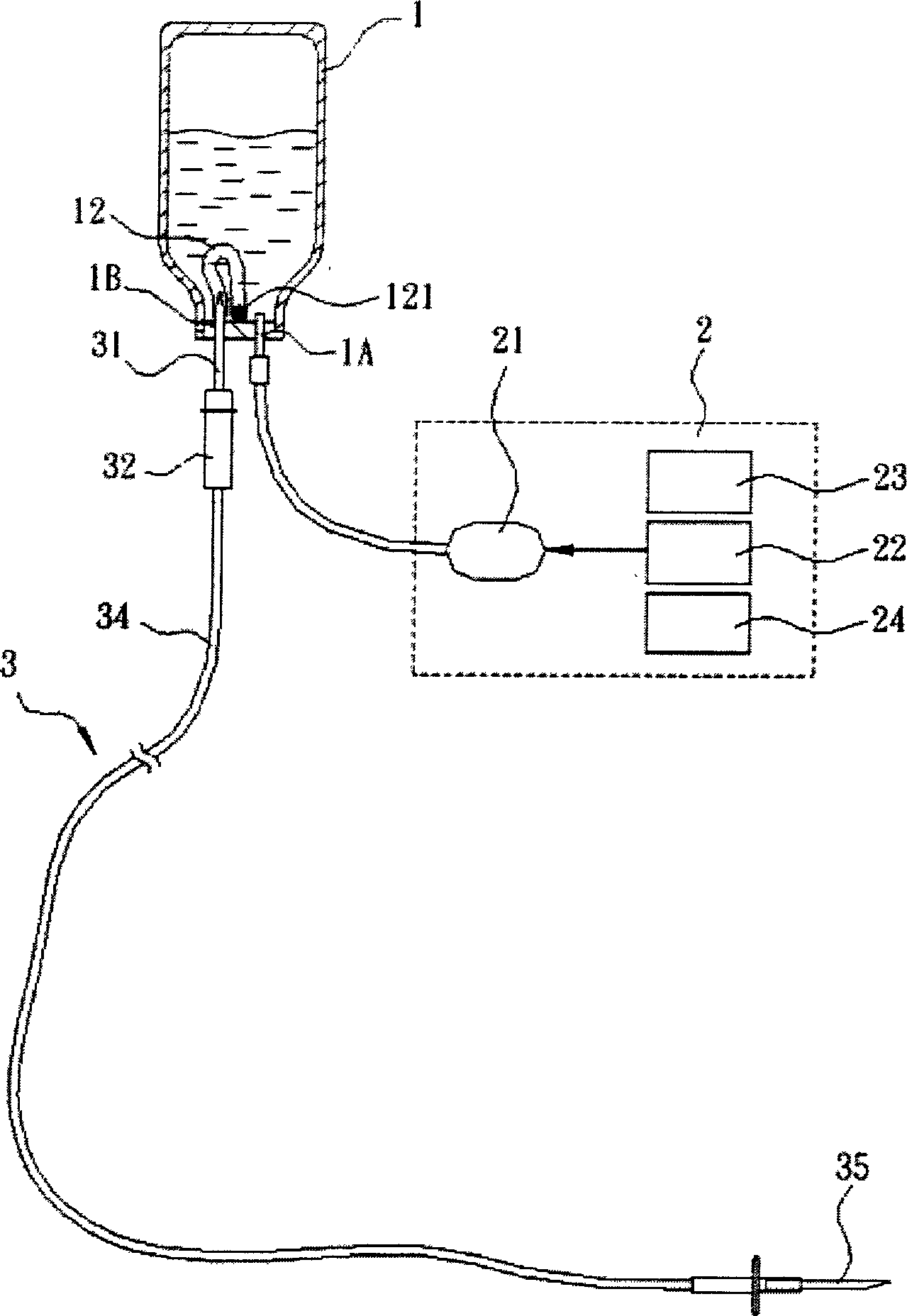
[0074] Please refer to figure 1 As shown, it is a structural diagram of a drip injection device, which at least includes:

[0075] A drop 1 contains at least one hydrophilic material 13, connected to the air-inflating / pumping dual-purpose motor 21 of the control device 2 through the contact point 1A, and inflates the drip 1 through the inflating / pumping dual-purpose motor 21 to inflate the drip 1 The liquid in it flows to the injection device 3;

[0076] A control device 2 at least includes an air charging / air pumping dual-purpose motor 21, a microprocessor 22, a wireless transmission device 23 and a warning device 24, which is to connect the air charging / air pumping dual-purpose motor 21 of the control device 2 with the drip 1 phase connection to provide gas; and

[0077] An injection device 3 at least includes an injection catheter connector 31, an accommodating groove 32 and an injection needle connector 35, wherein the injection catheter connector 31 is connected to the ...


PUM


Abstract

The invention discloses a drip injection device, which comprises the following parts: drip, control device and injection device, wherein the drip contains at least one hydrophilic material, which connects aerating-extracting motor of control device; the control device contains aerating-extracting motor, wireless transmission device, alarming device and microprocessor, which provides gas to drip; the injection device contains injection conduit joint, containing groove and injection needle joint; the injection conduit joint connects the drip through joint, which makes the liquid flow into the injection needle joint. The invention is convenient to operate, which improves the working efficiency.

Description

technical field [0001] The present invention relates to a drip injection device, which at least comprises a control device, a drip and an injection device, and the drip is inflated by an air-inflating / pumping dual-purpose motor of the control device to generate pressure. The liquid in the injection device flows to the injection device, and the injection catheter joint of the injection device is connected with the drip, so that the liquid in the drip flows through the injection catheter joint and along the injection tube to the injection needle joint. Background technique [0002] At present, the drip injection device on the market uses a bag-shaped or drip bottle injection method. The injection device must hang the drip high to use atmospheric pressure to inject the liquid in the drip along the catheter to the patient. Due to the high-hanging type The injection device is easy to cause blood backflow due to the carelessness of the patient. In addition, because the high-hangi...

Claims


Application Information

Patent Timeline
IPC IPC(8): A61M5/142
Inventor 杨章民
Owner 杨章民
Learn More