Siding boards attachment structure

A technology of structure and siding, applied in the direction of building structure, covering/lining, construction, etc., can solve the problems of reduced appearance design, easy cracks on outer siding, and reduced construction efficiency, etc., and achieve the effect of superior constructability

Inactive Publication Date: 2006-08-02
NICHIHA CORP
View PDF0 Cites 3 Cited by
  • Summary
  • Abstract
  • Description
  • Claims
  • Application Information

AI Technical Summary

Problems solved by technology

[0008] However, when nailing is performed on the above-mentioned dimension adjustment outer wall panel 920, no matter where it is performed, the appearance design property will be deteriorated.
That is, especially for other parts, a good appearance can be ensured by carrying out metal work using the stopper metal parts 95, but since the part which is difficult to carry out metal work as described above, it is necessary to carry out nail work, thereby, resulting in Decline in appearance design
[0009] In addition, in order to improve the appearance, the nail part needs to be repaired and painted later, which leads to a decrease in construction efficiency and increases construction cost.
In addition, if nailing is performed, there may be cracks or defects in the outer wall panel, which may cause water leakage from the nailed part.
[0010] Furthermore, when a material as hard as a fired base material is used as the outer wall panel, damage such as cracks may easily occur on the outer wall panel due to nailing.
[0011] The above-mentioned problems are not limited to the junction with the lower roof, but may also occur on the upper side or lower side of the opening, or at the eaves, and other construction sites where size-adjustable outer wall panels are used.

Method used


Image

  • Siding boards attachment structure
  • Siding boards attachment structure
  • Siding boards attachment structure

Examples


Embodiment 1

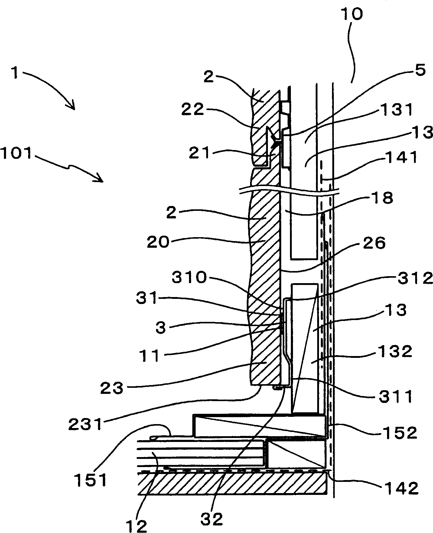
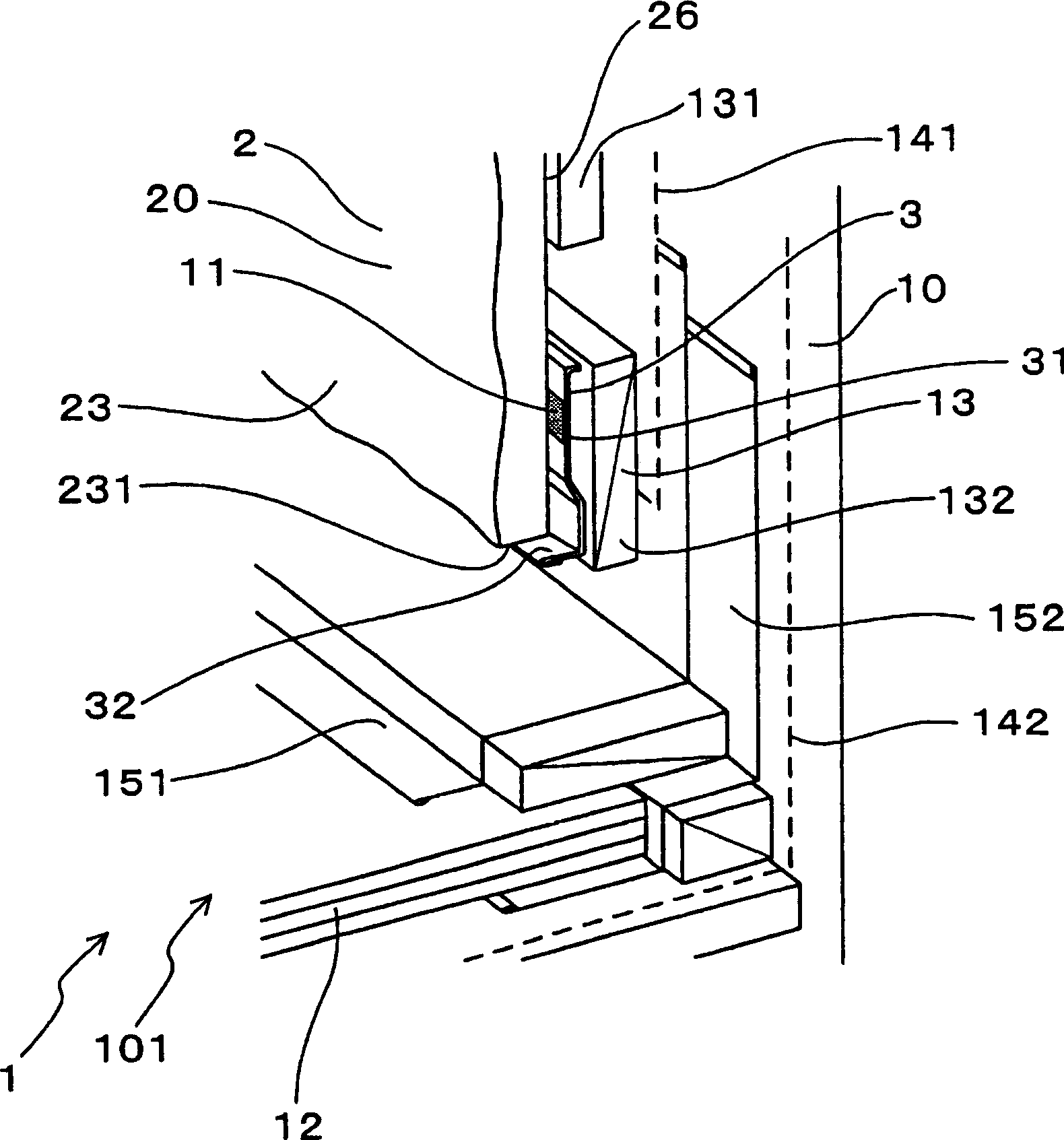
[0057] use Figure 1 to Figure 6 The outer wall construction structure of the embodiment of the present invention will be described.

[0058] The outer wall construction structure 1 of the present embodiment, such as figure 1 , Figure 4 As shown, a plurality of outer wall panels 2 are spliced ​​up and down and joined, and at the same time, they are fixed on the structural body 10 of the building by the stop metal piece 5 .

[0059] In the state where the upper lower wedge 21 formed on the upper side of the outer wall panel 2 arranged on the lower side and the lower upper wedge 22 formed on the lower side of the outer wall panel 2 arranged on the upper side are locked, the stop metal fitting 5 is fixed to the structure. Body 10 on.

[0060] Such as Figure 1 ~ Figure 3 As shown, among the above-mentioned plurality of outer wall panels 2 , the lower upper wedge 22 is cut off from the size adjustment outer wall panel 20 having the truncated end portion 23 which cuts off the...

Embodiment 2

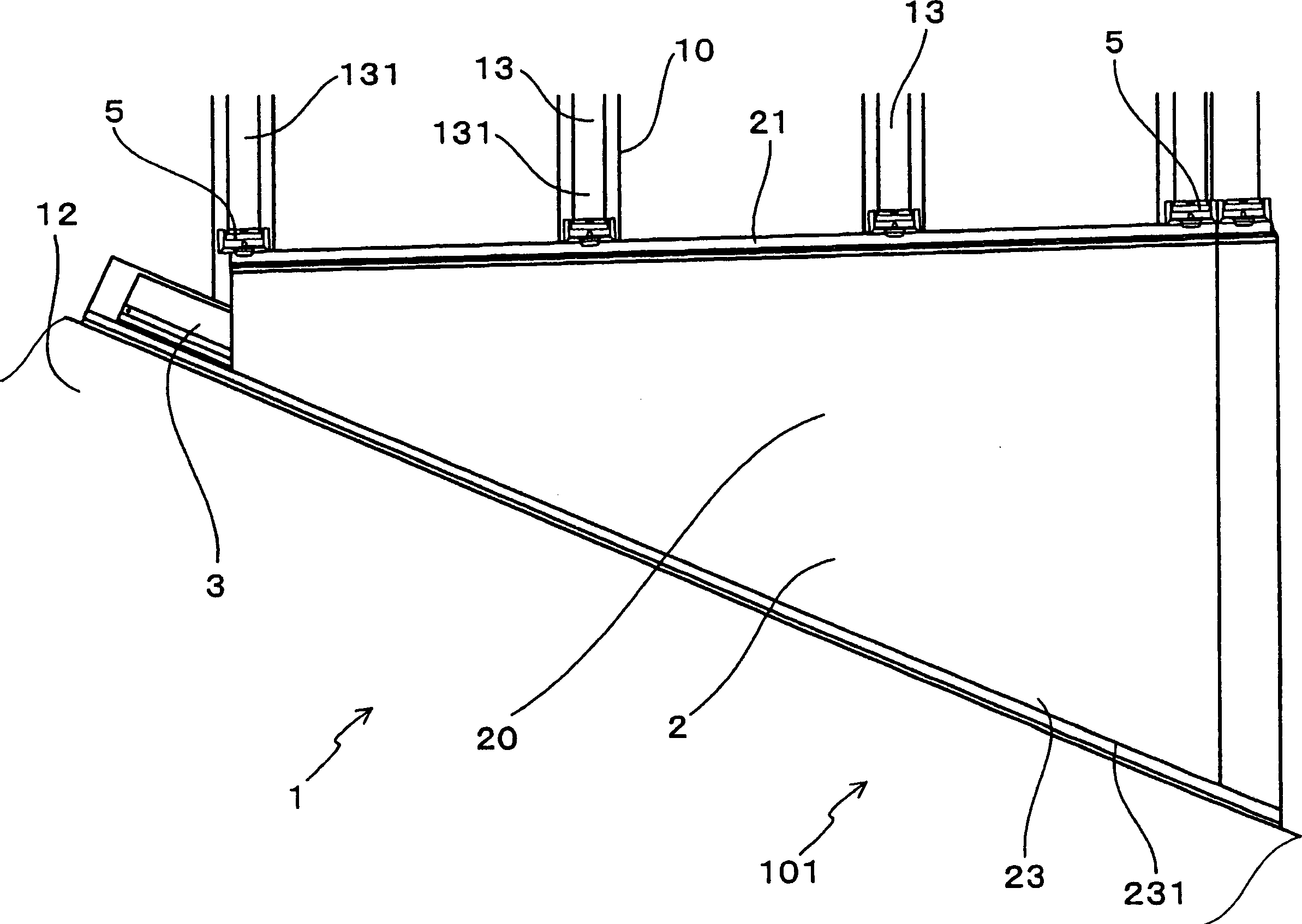
[0090] Such as Figure 7 , Figure 8 As shown, the present embodiment is an example of the outer wall construction structure 1 of the joint portion 102 on the beam side of the lower roof 12 .

[0091] That is, the end portion construction metal fitting 3 is disposed on the cut-off end portion 23 of the size-adjusting outer wall panel 20 disposed on the above-mentioned joint portion 102 .

[0092] In this embodiment, a front waterproof paper 141 and a piece of flashing 15 and a rear waterproof paper 142 are interposed between the battens 13 and the construction body 10 .

[0093] Others are the same as in Embodiment 1.

[0094]In the case of this embodiment, the design and weather resistance of the joint portion 102 on the beam side that is jointed with the lower roof 12 can be improved.

[0095] In addition, it has the same effect as Example 1.

Embodiment 3

[0097] Such as Figure 9 , Figure 10 As shown, this embodiment is an example of the outer wall construction structure 1 on the upper side of the opening 16 where windows and the like are arranged.

[0098] That is, the end portion construction metal fitting 3 is disposed on the cut-off end portion 23 of the dimension adjustment outer wall panel 20 disposed above the opening portion 16 .

[0099] In addition, a window frame 161 is disposed above the opening 16 , and above the window frame 161 , the horizontal slats 132 and the size-adjusting outer wall plate 20 are disposed. The size adjustment outer wall panel 20 is cut along the shape of the opening 102 , and the cut end 23 is arranged on the upper side of the opening 102 .

[0100] In addition, the end part construction metal fitting 3 is arrange|positioned at this cut-off end part 23. As shown in FIG.

[0101] In addition, a sealing material 163 is driven between the cut-off end portion 23 and the window frame 161 , and...


PUM


Abstract

The exterior wall construction structure 1 is formed by stopping an exterior wallboard 2 to a structure skeleton 10 with a stopping metal fitting 5 while making vertical shiplap connection. The stopping metal fitting 5 interlocks an upper part lower tongue 21 of the exterior wallboard 2 placed on the lower side with a lower part upper tongue 22 placed on the upper side. The cutting end 23 of a dimension adjusting exterior wallboard 20 among a plurality of exterior wallboards 2 is fixed to the structure skeleton 10 through an end construction metal fitting 3. The end construction metal fitting 3 has a back board 31 fixed to the structure skeleton 10 and a forward bending section 32 bent forward from one end thereof. The end construction metal fitting 3 is made to abut on the back board 31 on the back side 26 of the dimension adjusting exterior wallboard 20, and the forward bending section 32 is made to abut on the cutting end face 231 of the dimension adjusting exterior wallboard 20. The back board 31 and the back side 26 of the dimension adjusting exterior wallboard 20 are adhered to each other with an adhesive 11.

Description

technical field [0001] The invention relates to an outer wall construction structure formed by splicing and joining a plurality of outer wall panels up and down and fixing them on the structure body through stop metal pieces. Background technique [0002] Such as Figure 15 , Figure 16 As shown, conventionally, there is an outer wall construction structure 9 in which an outer wall panel 92 is fixed to a slat 93 fixed to a structural body 90 of a building constituted by pillars or girders. [0003] In this outer wall construction structure 9 , the lower upper wedge 922 of the outer wall panel 92 arranged on the upper side and the upper lower wedge 921 of the outer wall panel 92 arranged on the lower side are locked by the stopper metal fittings 95 . Also, the stop metal piece 95 is fixed on a slat 93 fixed to the construction body 90 by screws 94 . As a result, the outer wall panel 92 is fixed to the structural body 90 by means of the battens 93 . [0004] stop metal piec...

Claims


Application Information

Patent Timeline
Patent Type & Authority Applications(China)
IPC IPC(8): E04F13/07E04F13/21
CPCE04F13/0821E04F13/0885
Inventor 伊藤恒明
Owner NICHIHA CORP
Why Eureka
Try Eureka