Formboard supporting rod

A technology of formwork support and support rods, which is applied to the joints of formwork/formwork/work frame, the preparation of building components on site, construction, etc., which can solve the problems of inconvenient installation, insufficient penetration position, and difficult alignment.

Inactive Publication Date: 2006-08-09
SUCOOT IND CO LTD
View PDF0 Cites 0 Cited by
  • Summary
  • Abstract
  • Description
  • Claims
  • Application Information

AI Technical Summary

Problems solved by technology

Yet outside these perforations, the plane 12 of support bar still has a lot of unperforated positions, and its unperforated area exceeds the area of ​​these perforations, causes the penetrating position to be insufficient, when the operator wants When screw rods are threaded between the support rods, it is often difficult to align the perforations 15 of the two support rods, causing inconvenience in installation.

Method used


Image

  • Formboard supporting rod
  • Formboard supporting rod
  • Formboard supporting rod

Examples


Embodiment Construction

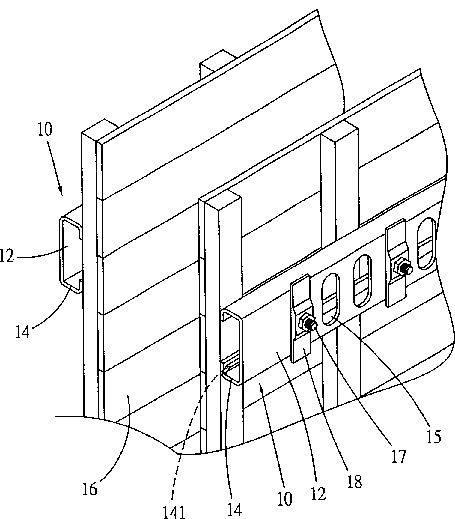
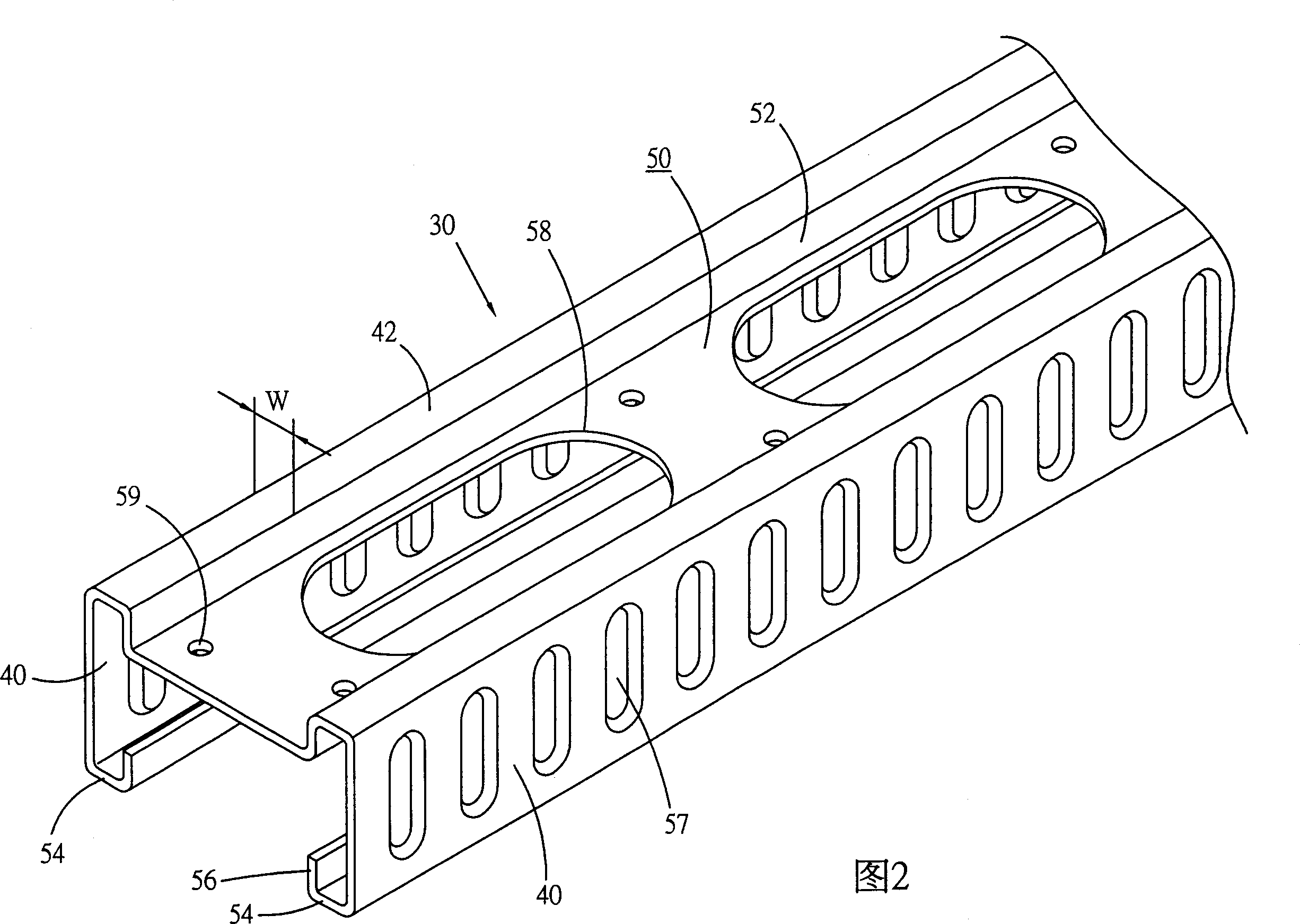
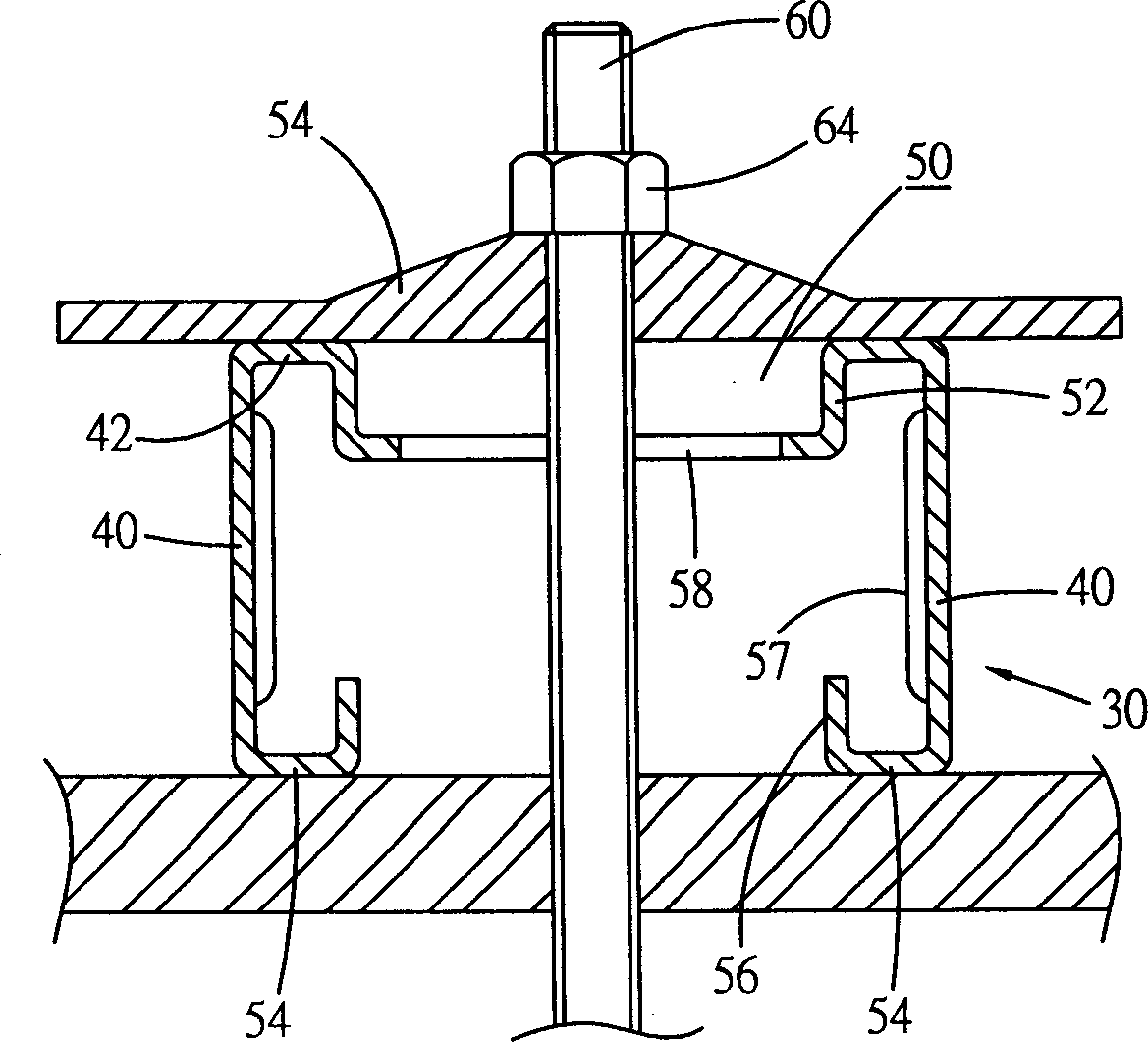
[0025] First please refer to FIG. 2 , which shows a preferred embodiment of the support rod 30 provided by the present invention. The support rod 30 is made of metal, has a single cross-sectional shape, and its cross-sectional structure includes:

[0026] Two upright walls 40 are parallel and keep a proper distance.

[0027] A top wall 42 is located between the two upright walls 40 and is horizontally connected to top edges of the two upright walls.

[0028] A concave space 50 is recessed from the top wall 42 from top to bottom along the axial direction of the support rod. The concave space 50 is located right at the center of the support bar, and two sides of the concave space 50 respectively form an upright small sidewall 52 , and the two small sidewalls 52 maintain a proper distance from the two upright walls 40 .

[0029] The two bottom walls 54 extend horizontally inward from the bottom ends of the two upright walls 40 . Each bottom wall 54 has a free edge and extends ...


PUM


Abstract

Present invention refers to templet stand bar whose section structure containing two upright walls, a upper wall crosslinking top edge of said two upright walls, a inner concave space with stand-up minor wall in two sides, respectively keeping relevance interval with said two upright walls, preset number of punch hole located lower wall of said inner concave, two base walls inward extended from said upright walls bottom. Said stand bar has preferred whole intensity.

Description

technical field [0001] The present invention relates to an article for construction, and specifically refers to a formwork support rod with better structural strength and use effect. Background technique [0002] Usually, such as figure 1 As shown, a known formwork support rod 10 has a cross section that is roughly C-shaped and has: a plane 12 and two side walls 14 connected to the two long sides of the plane 12, and several perforations are arranged at equal intervals on the plane 12 15. [0003] During use, two support rods 10 are placed on the outer sides of the two templates 16 respectively, and then the perforations 15 of the template 16 and the support rods are pierced with some screw rods 17, and then fixed at each screw rod 17 two ends with two fixers 18, so that The supporting rods 10 are used to support the formwork so as to bear the pressure of grouting when grouting between the formworks. After grouting, the hard bodies of buildings such as walls are formed. ...

Claims


Application Information

Patent Timeline
Patent Type & Authority Applications(China)
IPC IPC(8): E04G17/14
Inventor 施龙井
Owner SUCOOT IND CO LTD
Why Eureka
Try Eureka