
Bill discrimination apparatus

A banknote and transmission path technology, which is applied in the field of banknote identification devices, can solve the problems of device enlargement and inability to configure target sensors, etc.

Inactive Publication Date: 2006-08-16
HITACHI OMRON TERMINAL SOLUTIONS CORP
View PDF1 Cites 22 Cited by
  • Summary
  • Abstract
  • Description
  • Claims
  • Application Information

AI Technical Summary

Problems solved by technology

However, in the case of providing a space for preventing interference and arranging magnetic sensors or optical sensors consecutively, it becomes a problem of arranging a plurality of sensors and increasing the size of the device
Alternatively, it is not possible to configure all target sensors

Method used


Image

  • Bill discrimination apparatus
  • Bill discrimination apparatus
  • Bill discrimination apparatus

Examples


Embodiment Construction

[0025] Hereinafter, preferred embodiments of the present invention will be described in detail with reference to the drawings. In addition, this does not limit the present invention.

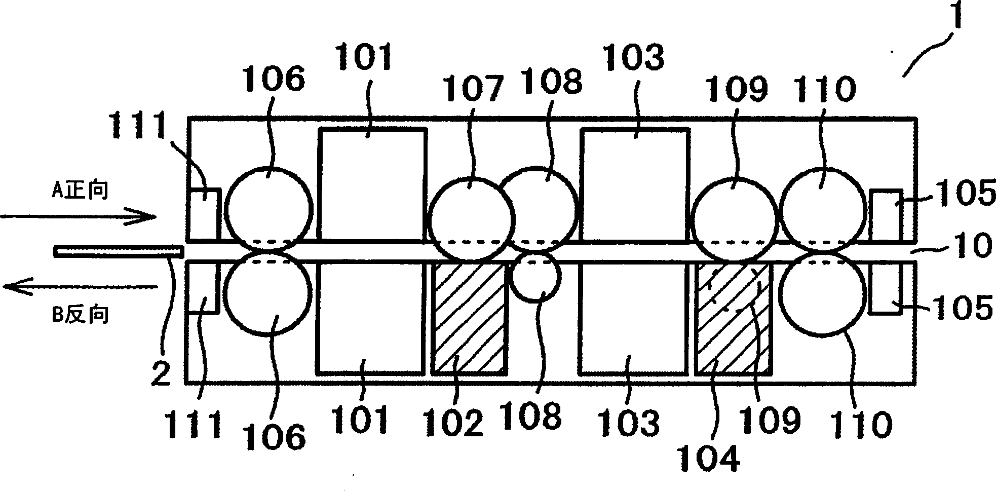
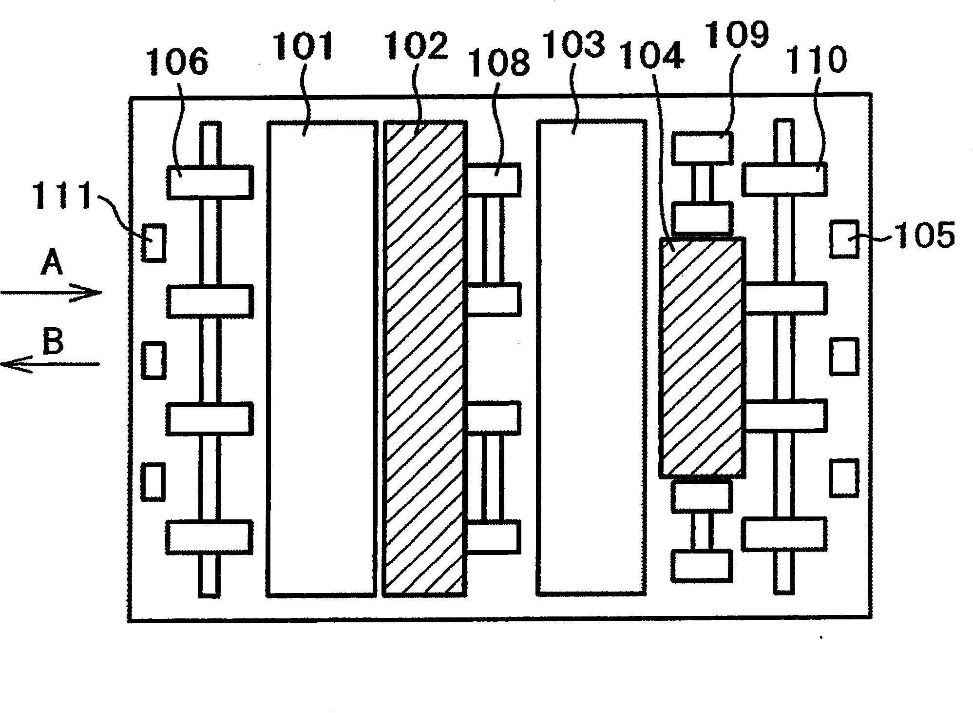
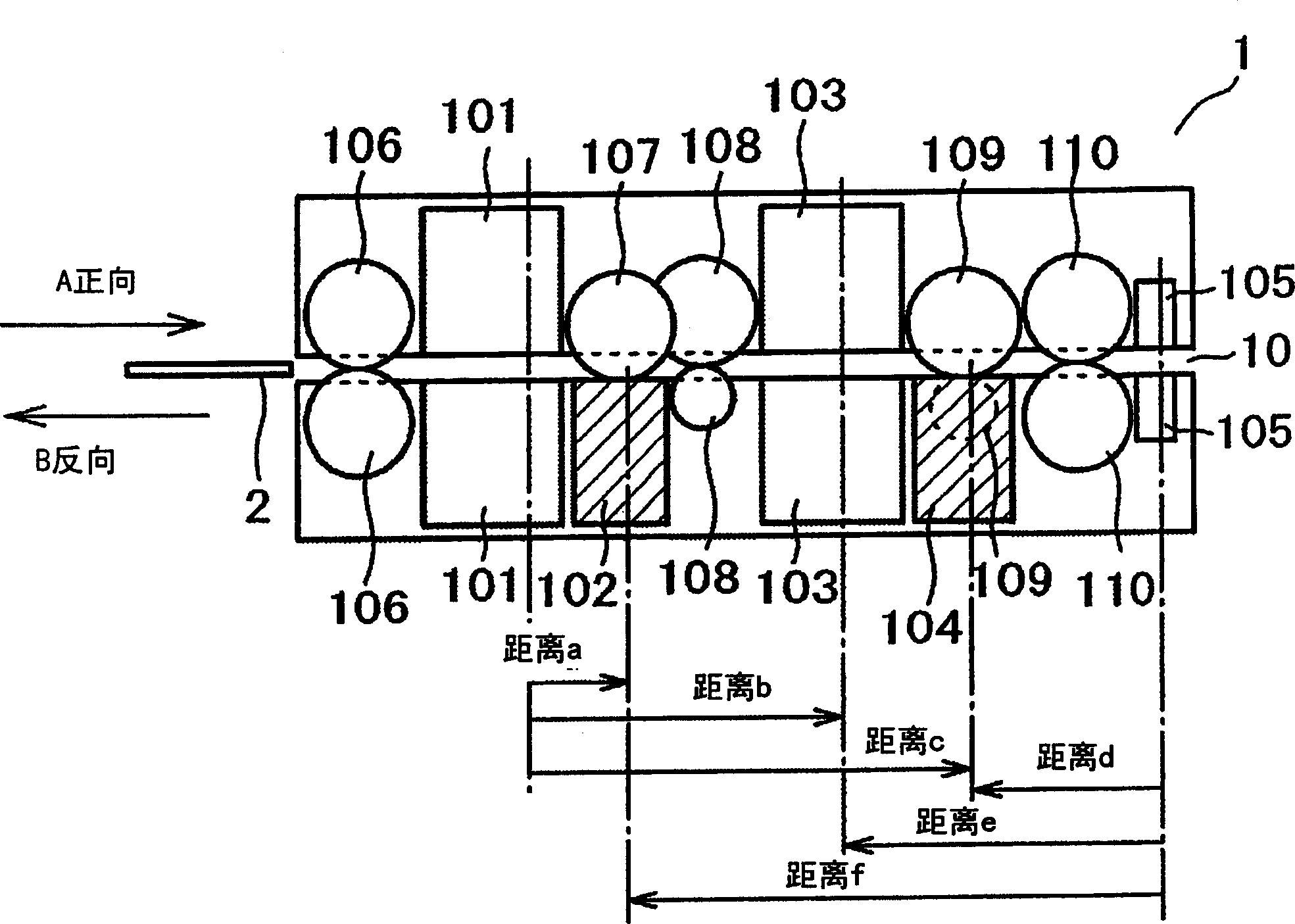
[0026] figure 1 is a side view of a banknote identification device to which one embodiment is applied, figure 2 is its top view. A plurality of rollers 106 to 110 are arranged on the conveying path 10 of the banknote discriminating device 1, and these conveying rollers are rotationally controlled according to a control signal from a control unit (not shown), so that the paper currency can be conveyed in two directions of forward A and reverse B. banknotes. In the banknote discriminating device of this example in which banknotes are transported in two directions, currency type determination, authenticity determination, and integrity determination are performed by processing information obtained from the banknotes during forward A and reverse B transport of the banknotes. Wait for processing....


PUM


Abstract

The invention discloses a banknote discrimination apparatus, which can discriminate banknotes according to detection signals obtained by sensors arranged on a transport path from a banknote transported on the transport path. The banknote discrimination apparatus comprises a plurality of different magnetic sensors (102, 104) for detecting the magnetic characteristic of the banknote and a plurality of optical sensors (101, 103) for optically detecting the banknote, which are alternately arranged on the transport path.

Description

technical field [0001] The present invention relates to a banknote discriminating device, and in particular to a banknote discriminating device used in an automatic cash deposit and withdrawal device (hereinafter referred to as ATM) for depositing and withdrawing banknotes. Background technique [0002] The ATM is equipped with a banknote identification device for determining the currency type, authenticity, integrity, etc. of the banknotes, and performs identification of the banknotes conveyed on the conveying path. In the identification of banknotes, in order to detect the size of the banknotes and the reflected light and transmitted light from the surface of the banknotes, or to detect the magnetic characteristics of the magnetic ink used in the printing of banknotes, several optical sensors or magnetic sensors are arranged. [0003] For example, in Japanese Patent Laid-Open Publication No. 9-245217, it is disclosed that in the banknote identification device, a line senso...

Claims


Application Information

Patent Timeline
Patent Type & Authority Applications(China)
IPC IPC(8): G07D7/04G07D7/12G07D7/00
CPCG07D7/12G07D7/04G07D7/20G07D7/121G07D11/225G07F19/202G07D2207/00G07D2211/00
Inventor 森崎智光水野英治加藤笃史
Owner HITACHI OMRON TERMINAL SOLUTIONS CORP
Learn More