Plug seat

A socket and insert technology, applied in the direction of contact parts, fixed/insulated contact members, etc., can solve the problem of shell thickness (height becomes larger, etc.)

Inactive Publication Date: 2006-08-16
MATSUSHITA ELECTRIC WORKS LTD
View PDF0 Cites 6 Cited by
  • Summary
  • Abstract
  • Description
  • Claims
  • Application Information

AI Technical Summary

Problems solved by technology

Therefore, the length of the insertion piece to accommodate the reed is longer, whi

Method used


Image

  • Plug seat
  • Plug seat
  • Plug seat

Examples


no. 1 example

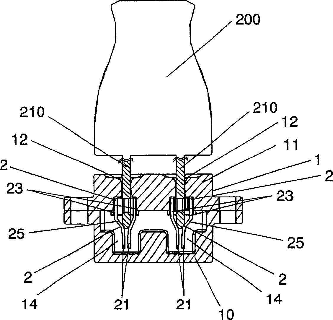
[0058] The socket according to the first embodiment of the present invention is a wall socket installed in a wall with its front surface exposed to the outside. Such as figure 1 As shown, the socket includes: a housing 1, which has two paired slots 12 on its front surface, for inserting the flat insert 210 of the plug 200; and the insert accommodation reed 2, which is installed in the housing , used to accommodate the flat insert inserted into the housing 1 from the slot 12, and electrically connected to the wires (not shown) extending from the outside.

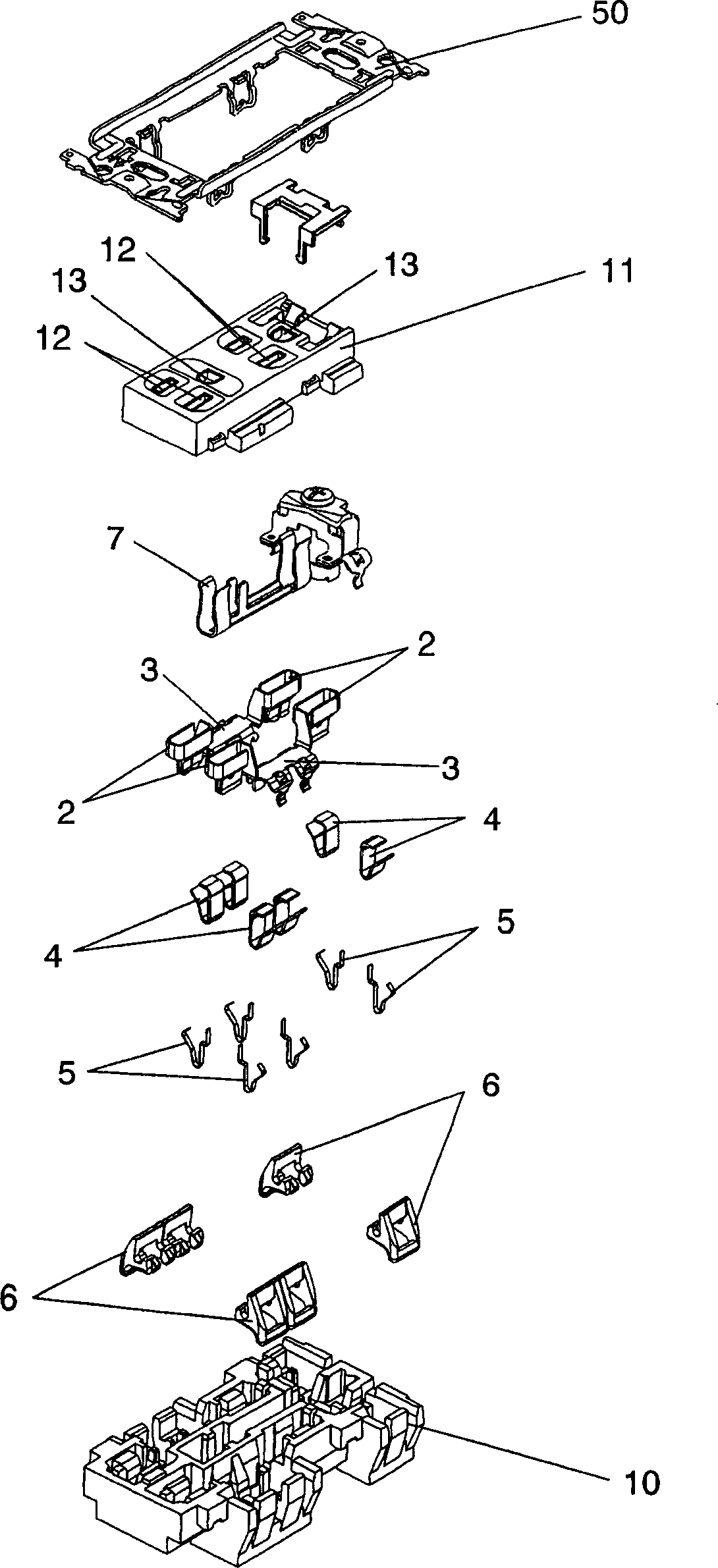
[0059] Such as figure 2 As shown, the housing 1 has an open front surface (in figure 2 The plastic box-type main body 10 of the upper surface in), and the plastic cover plate 11 that covers the front surface of the main body 10 and has a slot 12 on its front surface. The main body 10 and the cover plate 11 are connected to each other by an assembly frame 50 which also serves as an installation frame for installing the s...


PUM


Abstract

To provide a receptacle in which inadvertent electric shock can be prevented, and furthermore the thickness of the case can be made thinner. The receptacle has a case 1 which has a plug blade insertion port 12 for inserting a flat plug blade 210 of the plug in the front and a plurality of blade receiving springs 2 which are housed in the case and receive the flat plug blade inserted into the plug blade insertion port and are electrically connected to an electric wire extending from the outside. Each of blade receiving spring 2 is composed of a pair of spring pieces 21 mutually opposed with a prescribed distance in order to interpose the flat plug blade and a frame 2 to support the pair of spring pieces 210. The frame 2 is composed of a pair of side pieces 23 mutually opposed to each other with a distance wider than that of the pair of spring pieces, a connecting piece 24 which connects the pair of side pieces at the side, and a jointing piece 25 which is provided extended from the rear end on the opposite side to the plug blade insertion port of each side piece, and the pair of spring pieces 21 are extended from the rear end on the opposite side to the plug blade insertion port of each jointing piece.

Description

technical field [0001] The invention relates to a socket for a plug having a flat blade. Background technique [0002] Japanese Unexamined Patent Application Publication No. 10-326658 discloses a socket for a plug having flat blades. This socket is a wall socket which is installed in the wall with the front surface exposed. The socket includes: a housing (case), which has blade slots (blade slots) on the front surface, and is used to insert flat blades of the bolt; and a plurality of blade receiving springs (blade receiving springs), which hold In the housing, the flat insertion piece is used to accommodate the insertion piece inserted into the housing from the insertion piece slot, and is electrically connected to the wire extending from the outside. [0003] Such as Figure 28 As shown, the conventional insert receiving reed 110 includes a pair of spring pieces (a pair of spring pieces) 120 opposed to each other according to a predetermined distance for clamping each ins...

Claims


Application Information

Patent Timeline
IPC IPC(8): H01R13/11H01R13/40
Inventor 桥本升近藤真树本田稔氏原秀哲加藤一佑岛冈国康今井克哉
Owner MATSUSHITA ELECTRIC WORKS LTD
Why Eureka
Try Eureka