Directional display apparatus

A technology of directional display and directional distribution, applied in the directions of instruments, optics, electrical components, etc., can solve problems such as the reduction of display brightness, and achieve the effect of minimum cost

Active Publication Date: 2006-08-23
AU OPTRONICS CORP
View PDF6 Cites 60 Cited by
  • Summary
  • Abstract
  • Description
  • Claims
  • Application Information

AI Technical Summary

Problems solved by technology

Outside the viewing window, the viewer will see inter-pixel gaps and the display will be reduced in brightness

Method used


Image

  • Directional display apparatus
  • Directional display apparatus
  • Directional display apparatus

Examples


Embodiment Construction

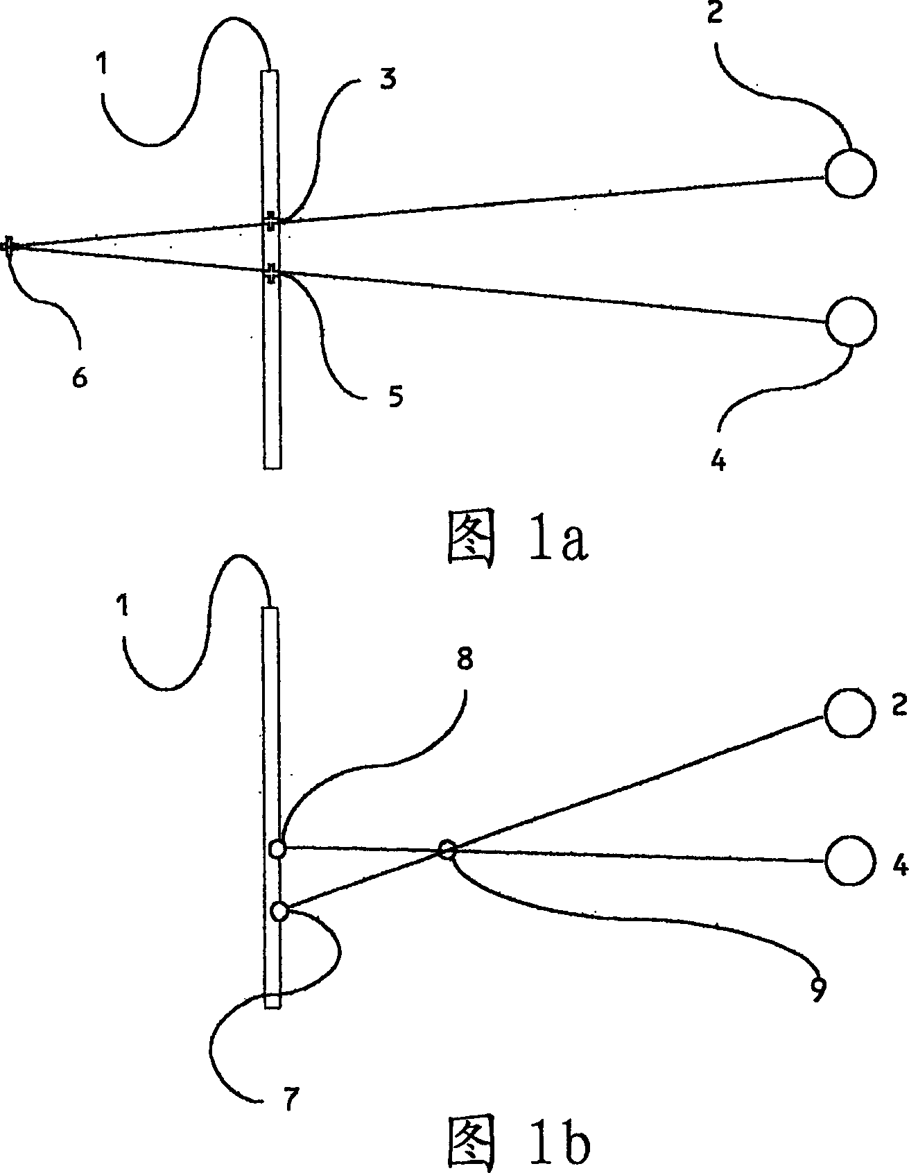
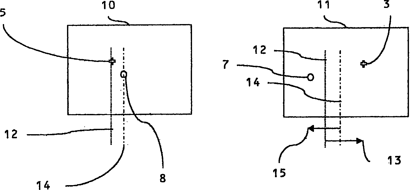
[0119] Some different embodiments employ common elements, for the sake of simplicity, these common elements will be given common reference numerals and their description will not be repeated. In addition, descriptions of elements in each embodiment are equally applied to the same elements in other embodiments, and to elements having corresponding effects mutatis mutandis. Additionally, the figures illustrating embodiments of the display show only a portion of the display for clarity. In fact, this structure can be repeated over the entire area of ​​the display.

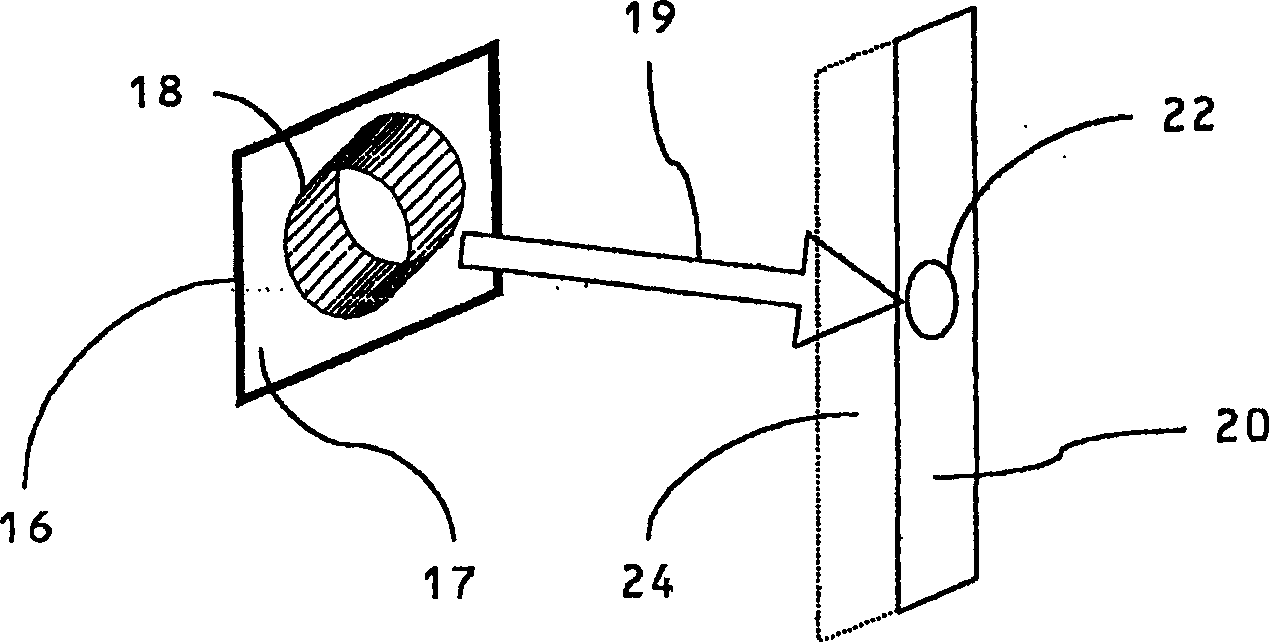
[0120] In this specification, the optical axis direction (director direction, or extraordinary axial direction) of a birefringent material will be referred to as a birefringent optical axis. It should not be confused with the optical axis of a lens, which is defined in the usual manner in geometric optics.

[0121] A cylindrical lens describes a lens in which an edge (which has a radius of curvature and possibly oth...


PUM

PropertyMeasurementUnit
heightaaaaaaaaaa
thicknessaaaaaaaaaa
thicknessaaaaaaaaaa

Abstract

A bireffingent lens structure comprises a birefringent lens array capable of directing light of a given polarisation into a directional distribution, the bireffingent lens comprising a solid bireffingent material and an isotropic material having an interface having a refractive structure. A switchable liquid crystal layer capable of rotating the polarisation of light passing therethrough is arranged adjacent the first bireffingent material. The interface between the bireffingent material and the liquid crystal layer has an alignment microstructure providing alignment of the bireffingent material and the liquid crystal layer. A pair of electrodes for applying an electric field to switch the liquid crystal are arranged with both the lens array and the switchable liquid crystal layer therebetween and a conductive material is incorporated in the lens array to reduce the voltage drop across the lens array. To reduce reflection, the interface between the bireffingent material and the isotropic material has an interface having alignment microstructure providing alignment of the bireffingent material, and the refractive index of the isotropic material is substantially equal to the extraordinary refractive index of the birefringent material.

Description

technical field [0001] The present invention relates to directional display devices and their manufacture. Background technique [0002] Such a device may be a switchable two-dimensional (2D) / three-dimensional (3D) autostereoscopic display device; a switchable high brightness reflective display system; or a multi-user display system. Such systems can be used in computer monitors, telecommunications handsets, digital cameras, laptop and desktop computers, gaming devices, automotive and other mobile display applications. [0003] Normal human vision is stereoscopic, meaning that each eye sees a slightly different image of the world. The brain combines the two images (called a stereo pair) to give the perception of depth. A stereoscopic three-dimensional display reproduces to each eye separate, generally planar images (corresponding to what one would see when viewing a real-world scene). The brain merges this stereo pair again to give the appearance of depth in the image. ...

Claims


Application Information

Patent Timeline
Patent Type & Authority Applications(China)
IPC IPC(8): G02B27/22H04N13/00G02F1/1333G02B30/25G02B30/28G02F1/29
CPCG02B27/26G02B27/225G02F1/133371G02B27/2214G02F1/29H04N13/0404G02F2203/28H04N13/305G02B30/25G02B30/28G02F1/133526G02F1/13363G02B30/27
Inventor 格雷厄姆·约翰·伍德盖特乔纳森·哈罗德
Owner AU OPTRONICS CORP
Why Eureka
Try Eureka