Connecting structure for parts in fuel tank made of resin

A connection structure and fuel tank technology, applied to the layout combined with the fuel supply of internal combustion engines, vehicle components, power plants, etc., can solve the problems of increasing the number of components and reducing manufacturing efficiency

Inactive Publication Date: 2006-09-06
YACHIYO IND CO LTD +2
View PDF1 Cites 6 Cited by
  • Summary
  • Abstract
  • Description
  • Claims
  • Application Information

AI Technical Summary

Problems solved by technology

However, the structure in which the O-ring 52 is inserted leads to an increase in the number of parts, thereby reducing manufacturing efficiency.

Method used


Image

  • Connecting structure for parts in fuel tank made of resin
  • Connecting structure for parts in fuel tank made of resin
  • Connecting structure for parts in fuel tank made of resin

Examples


no. 1 example

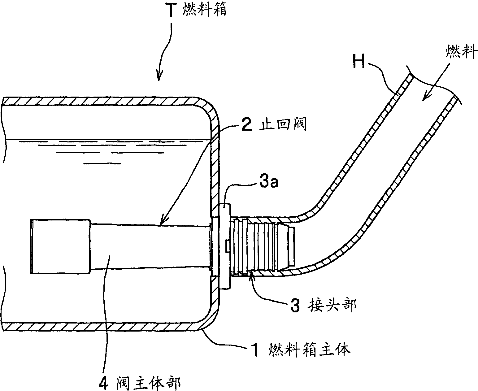
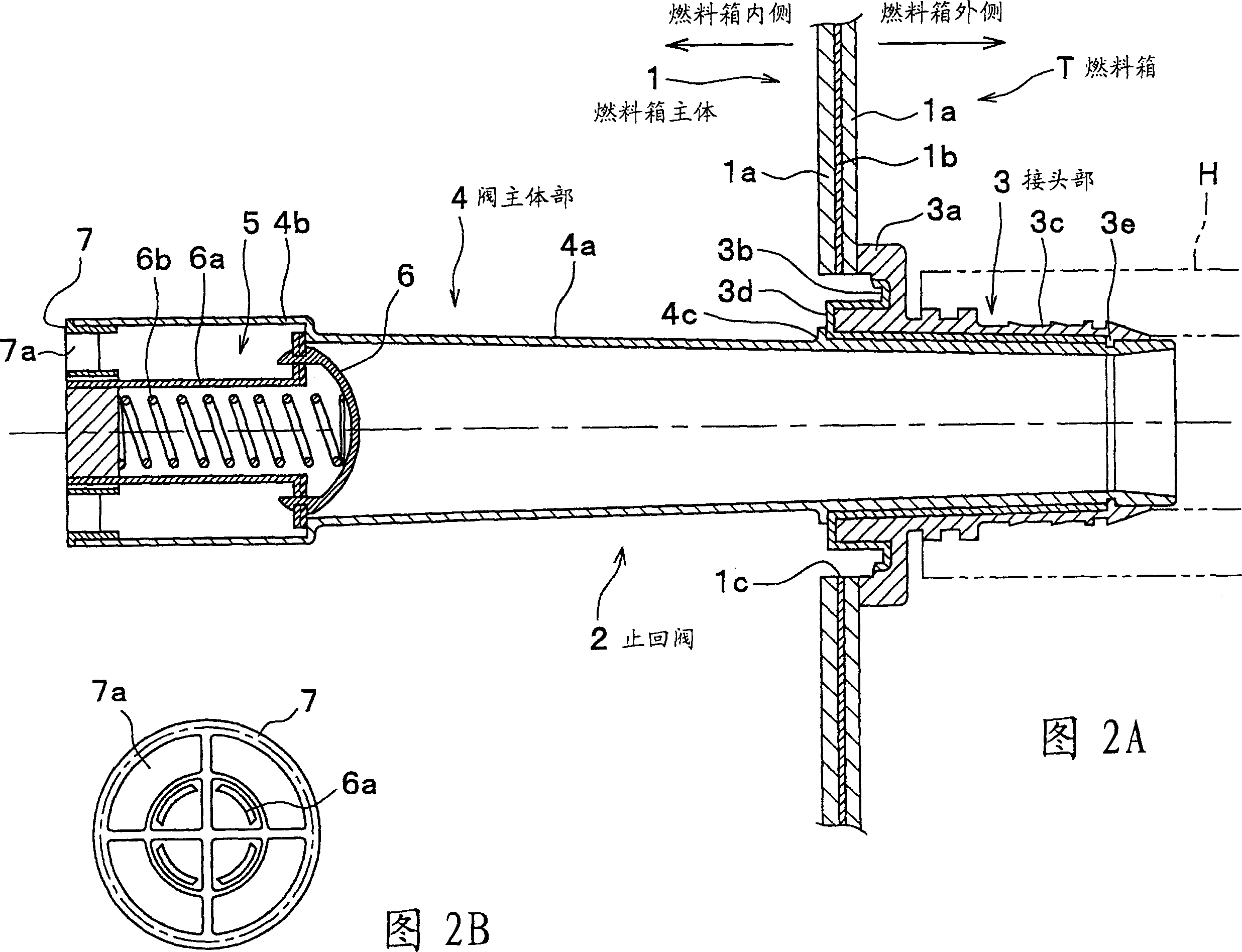
[0016] figure 1 It is a cross-sectional view showing the outer contour of the connection structure of the component (check valve 2) related to an embodiment of the present invention. Figure 2A and Figure 2B show figure 1 An enlarged view of the check valve shown in FIG. 2A is a cross-sectional view; and FIG. 2B is a front view viewed from the inside of the fuel tank. In these views, the fuel tank T includes a fuel tank main body 1 made of resin for storing fuel, and one side of the fuel tank main body 1 is connected to a check valve 2 for preventing fuel backflow. The check valve 2 includes a joint portion 3 connected to an outer peripheral edge portion of a through hole 1c formed on the side surface of the fuel tank body 1, and a cylindrical inner pipe (valve body portion 4) Supported by the joint part 3 and inserted into (contained in) the fuel tank main body 1. The fuel tank main body 1 is designed to have a cross-sectional shape in which, for example, an HC barrier layer 1b c...

no. 2 example

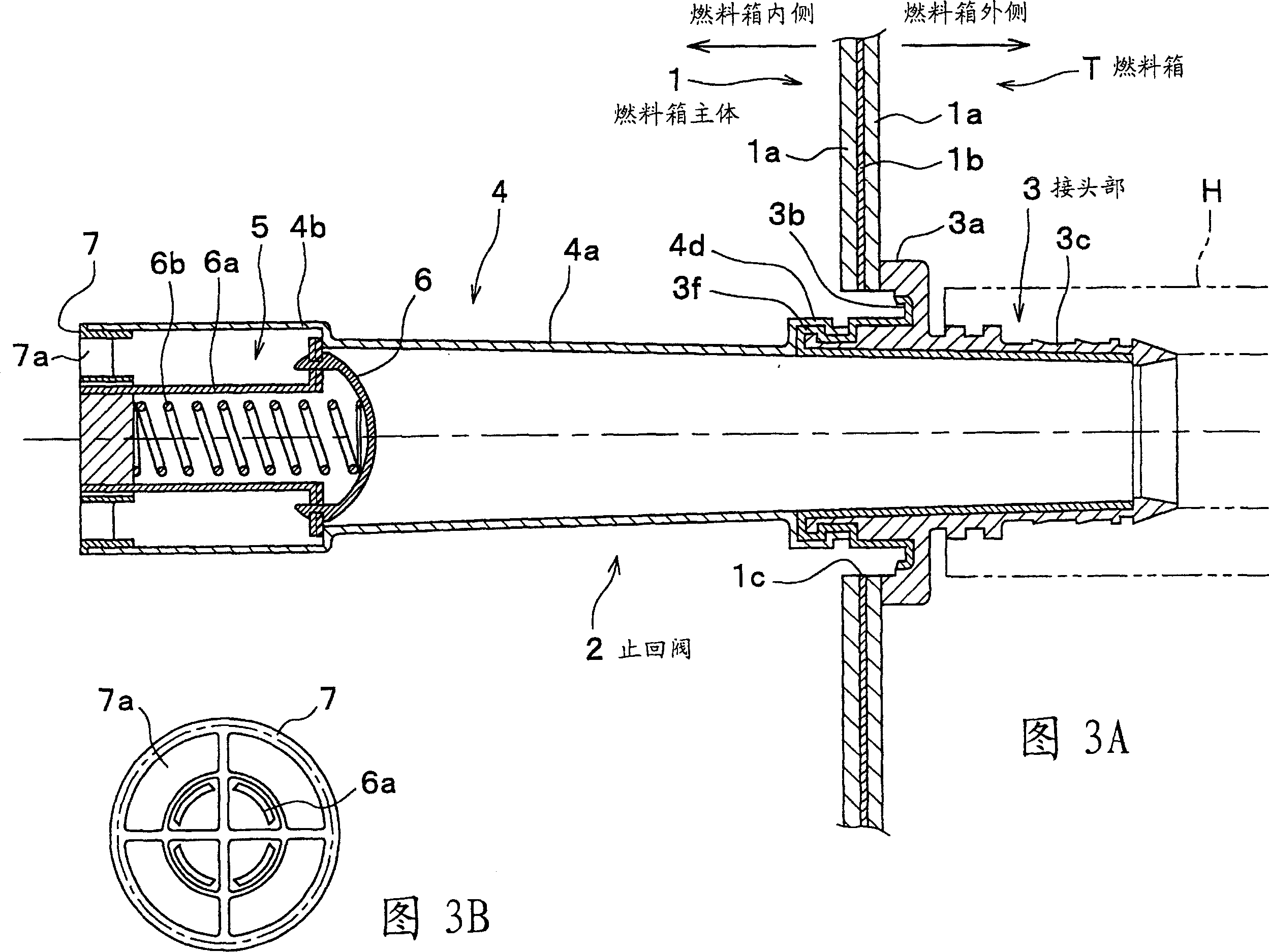
[0025] The second embodiment of the present invention will be described below. 3A and 3B are enlarged cross-sectional views showing the second embodiment. Meanwhile, in the second embodiment, the same reference numerals are used to denote the same elements as in the first embodiment, and the description thereof is omitted. The second embodiment is different from the first embodiment in the specific form of the motion adjustment mechanism. Although the first embodiment is designed in such a mode that the annular protrusion 3e is provided to be cut into the periphery of the tube middle part 4a on the side of the tube connecting tube part 3c, and so that the protrusion 4c (which is formed annularly at the periphery of the tube middle part 4a) Protruding toward the end surface 3d of the HC barrier material layer 3b facing the inner side of the fuel tank body 1, but the second embodiment is designed in such a mode that a hook-shaped claw is formed at the end of the tube middle part 4a ...


PUM


Abstract

The invention relates to a connection structure between the elements of resin fuel box. Wherein, the connection part is made from thermal deposition material, while said fuel box comprises a connecting head connecting the main body via thermal deposition, a inner tube supported by connecting head and contained inside the main body, and at least one motion adjuster at the connecting head and the inner tube to adjust the axial motion of inner tube along the connecting head. The connecting head and the inner tube are made by integrated molding.

Description

Technical field [0001] The present invention relates to a resin fuel tank to be mounted on automobiles and the like. Background technique [0002] Among fuel tanks mounted on automobiles, fuel tanks made of resin by blow molding have become mainstream in recent years from the viewpoint of, for example, corrosion protection and weight reduction. Generally, a variety of components are connected to the fuel tank, such as exhaust valves, check valves, and fuel pumps. The exhaust valve is used to lead the fuel vapor in the space above the liquid level to the outside of the fuel tank and keep the fuel tank inside. The pressure is constant, and the check valve is connected to the fuel injection pipe; and in the case where the fuel tank is made of resin, from the viewpoint of simplifying the manufacturing process, it is desirable to connect these components to the fuel tank body by thermal deposition. [0003] Fig. 4 is a partial cross-sectional view showing a connection structure of com...

Claims


Application Information

Patent Timeline
Patent Type & Authority Applications(China)
IPC IPC(8): B60K15/04
Inventor 吉泽勇司松崎彻村林真也金子直正谏山央中村忠久仲井俊显小关淳一山本升平
Owner YACHIYO IND CO LTD
Why Eureka
Try Eureka