Pipe bender

A bending processing and bending technology, which is applied in the field of pipe bending processing equipment, can solve problems such as troublesome and incapable of manufacturing accuracy, and achieve the effects of good operability, realizing feeding operation time, and compact structure

Inactive Publication Date: 2006-09-06
SANOH IND CO LTD
View PDF2 Cites 8 Cited by
  • Summary
  • Abstract
  • Description
  • Claims
  • Application Information

AI Technical Summary

Problems solved by technology

[0006] In the automatic pipe bending processing device, actuators are provided on the above-mentioned parts respectively, and the pipe can be bent three-dimensionally by controlling these actuators. However, when bending the pipe manually, all the above-mentioned operations must be performed manually. Not only is it troublesome, but it is also impossible to make high-precision tubes for unskilled workers.

Method used


Image

  • Pipe bender
  • Pipe bender
  • Pipe bender

Examples


Embodiment Construction

[0047] The present invention will be described below based on the embodiments shown in the drawings.

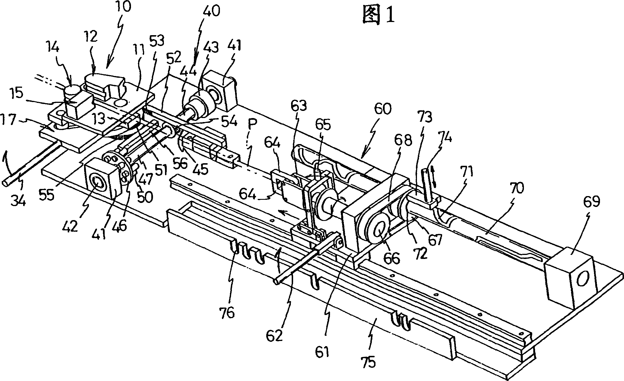
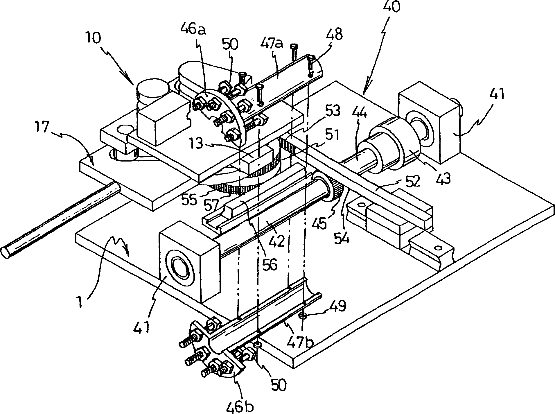
[0048] As shown in FIG. 1 , this pipe bending device includes: a bending unit 10 for bending a pipe, a bending angle setting unit 40 for determining the bending angle of the pipe, and a device for determining the feeding amount and bending direction of the pipe. The feed unit 60 and the like.

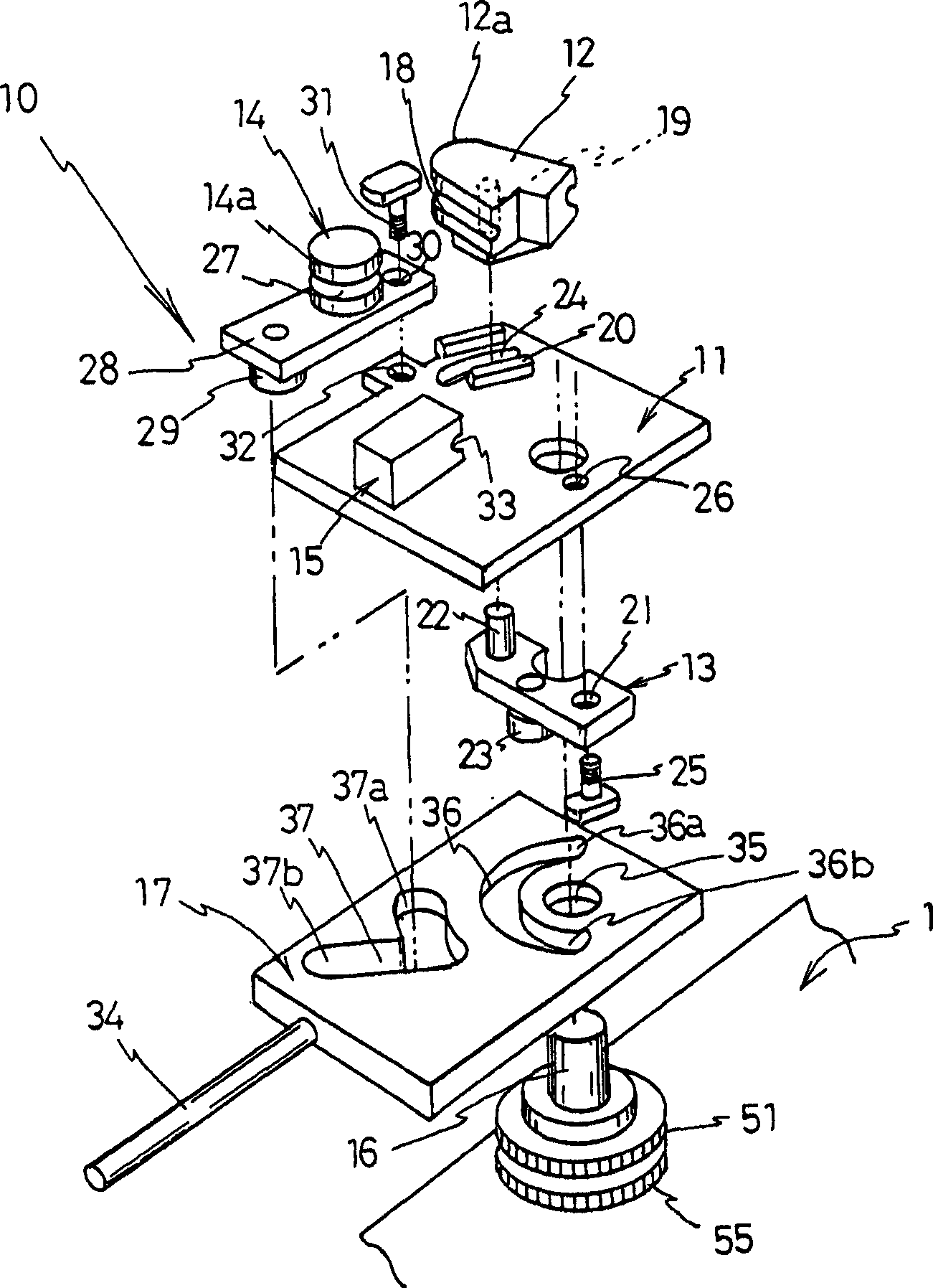
[0049] bend 10, such as figure 2 As shown in detail, the base plate 11 is provided with a gap above the frame 1 . The base plate 11 is provided with a bending die 12 , a bending die operating piece 13 , a pressure member 14 , and a jig 15 , and a shaft 16 is rotatably supported between the frame 1 and the base plate 11 . Furthermore, one end portion of the operation plate 17 is integrally provided on the shaft 16 .

[0050] The bending die 12 has a partially arc-shaped peripheral surface 12a, and an arc-shaped groove 18 for accommodating the pipe P is formed on the peripheral surfac...


PUM


Abstract

A pipe bender where the number of actuators can be reduced, operation is easily made even by hand, and even an unskilled user can produce a precisely bent pipe. A pipe bender where a pipe (P) is held by a clamp (15) and a bending die (12) with the pipe (P) received between the groove of the bending die (12) and the groove of a pressure (14) and in that state, the pressure (14) is rotated along the peripheral surface of the bending die (12) to bend the pipe (P). The bending die (12) is placed so as to be recedable from a bending point of the pipe (P). The bending die (12) is moved to the bending point in conjunction with bending operation by the pressure (14), and made to recede from the bending position in conjunction with return operation of the pressure (14).

Description

technical field [0001] The present invention relates to a pipe bending device, and more particularly to a pipe bending device suitable for manually bending a pipe. Background technique [0002] The basic configuration of the bending part of the pipe bending device is to include: a bending die that is arranged on a machine frame, has an arc-shaped peripheral surface, and has a groove formed on the peripheral surface, and is rotatable along the peripheral surface of the bending die. A pressure member provided on a machine frame having a groove at a position facing the groove of the bending die, and a state in which a tube is accommodated between the groove of the bending die and the groove of the pressure member provided on the frame This pipe is restrained by the jig of the above-mentioned bending die (for example, refer to Japanese Patent Application Laid-Open No. 10-211524 or Japanese Patent Laid-Open No. 2-284722). [0003] In addition, in such a pipe bending device, the ...

Claims


Application Information

Patent Timeline
IPC IPC(8): B21D7/024
CPCB21D7/024
Inventor 中里和彦关根善夫
Owner SANOH IND CO LTD
Why Eureka
Try Eureka