
Stapler

A stapler and staple technology, applied in the direction of nailing U-shaped nail tools, nailing tools, manufacturing tools, etc., can solve the problem of cutting sound and so on

Inactive Publication Date: 2006-09-06
MAX CO LTD
View PDF1 Cites 0 Cited by
  • Summary
  • Abstract
  • Description
  • Claims
  • Application Information

AI Technical Summary

Problems solved by technology

As a result, there is a problem of cutting sound during the peeling

Method used


Image

  • Stapler
  • Stapler
  • Stapler

Examples


Embodiment Construction

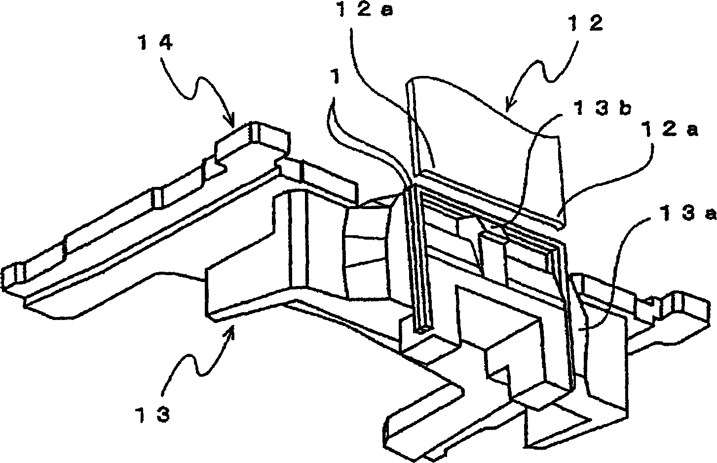
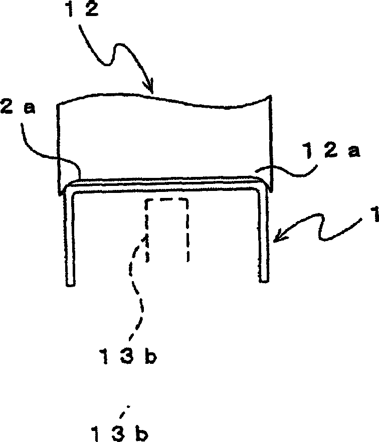
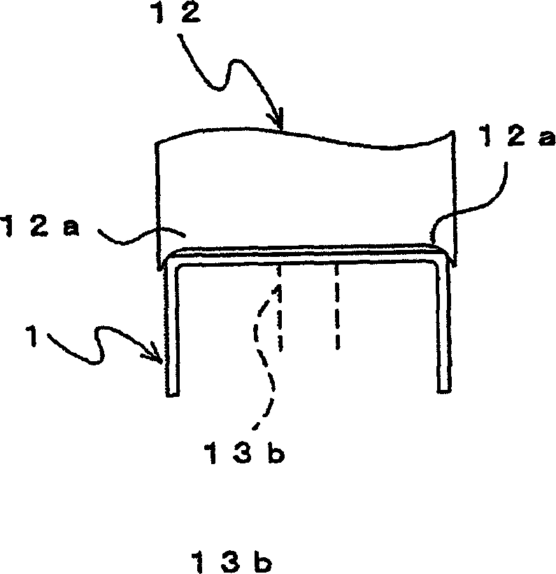
[0019] The invention is then illustrated by means of an electric stapler. Figure 1A It is a perspective view of the main part of the electric stapler, Figure 1B It is a front view of the main part of the initial state when the leading staple is separated from the next staple, Figure 1C It is a front view of the main part of the intermediate state when the most advanced staple is separated from the next staple, and FIG. 2A is the initial state when the most advanced staple is separated from the next staple. 2B is a cross-sectional view of a main part in a state in which the leading staple is separated from the next staple.

[0020] exist Figure 1A , Figure 1B and Figure 1C Among them, 1 is to form at least the most frontal staple into a roughly C-shaped staple; 12 is to separate the staple 1 from the next staple 1 and press it out so that both ends are inserted into the staple 13 is a pusher; 14 is a staple guide plate; 15 is a guide surface that guides the slide of ...


PUM


Abstract

A driver 12 is provided so that it can move up and down, and a C-shaped leading-end staple of sheet-shaped connected-staples 1 is pressed to a guide surface 15 by a pusher 13 so as to be opposed to a leading end of the driver 12. The pusher 13 includes a support surface 13b which is positioned near and under a center of the staple and protrudes so that one part of the support surface faces to an inside of at least the substantially C-shaped leading-end staple 1. Therefore, it is possible to prevent a cutting noise from being produced when the leading-end staple is torn off from the next staple in order to drive the leading-end staple in sheets of paper to be stapled.

Description

technical field [0001] The present invention relates to a stapler for binding sheets to be bound together at a desired position. Background technique [0002] Now, known is the device that is provided with stapler at stack tray (stack tray) etc. for copying machine, and this stapler staples the paper to be bound after copying at desired position (for example, Japanese Patent Document No. 2778460 Bulletin). [0003] In addition, such a stapler is equipped with a driver, which is lifted up and down on the upper frame of the bracket that is divided up and down through a connecting mechanism that is operatively connected by a driving part such as an electric motor or a reduction gear. C-shaped staples are driven into the bound paper stacked on the lower holder. [0004] On the other hand, when performing the driving, it is necessary to keep the leading-edge staple in the correct position, that is, to keep it in a proper position below the driver, and to restrain the leading-ed...

Claims


Application Information

Patent Timeline
Patent Type & Authority Applications(China)
IPC IPC(8): B27F7/38B25C5/04B27F7/19B27F7/21
CPCB27F7/19B27F7/38B27F7/36
Inventor 龟田太志
Owner MAX CO LTD
Learn More