
Electric lamp

A technology for electric lamps and light bulbs, which is applied to circuits, incandescent lamps, electrical components, etc., and can solve the problems of impossible and difficult to reduce the size of optical fiber lighting systems, and difficult to obtain light distribution characteristics.

Inactive Publication Date: 2006-09-06
KAHOKU LIGHTING SOLUTIONS CORP
View PDF1 Cites 2 Cited by
  • Summary
  • Abstract
  • Description
  • Claims
  • Application Information

AI Technical Summary

Problems solved by technology

However, with this adjustment, it is difficult and even impossible to obtain the desired light distribution characteristics
[0008] In addition, when the halogen lamp 100 in the figure is used, the reflector 102, which is a part unrelated to the bulb, is required, and this causes a problem that it is difficult to reduce the size of the optical fiber lighting system.

Method used


Image

  • Electric lamp
  • Electric lamp
  • Electric lamp

Examples


Embodiment Construction

[0048] Referring now to the accompanying drawings, embodiments of the present invention will be described in detail below.

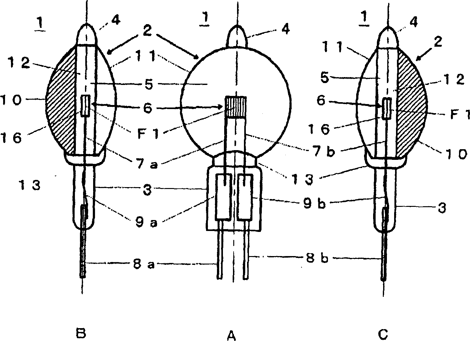
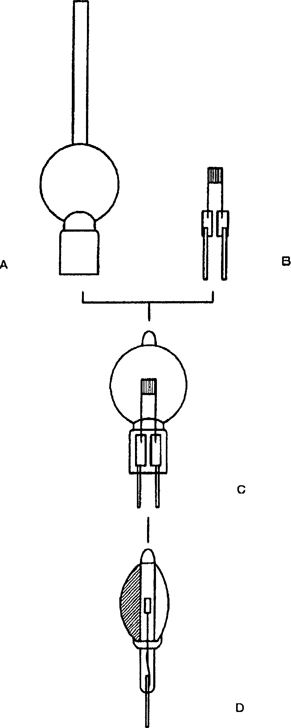
[0049] figure 1 Is a schematic diagram of a first embodiment of an electric lamp according to the invention, wherein A shows a front view, B is a left view and C is a right view; the electric lamp 1 in this embodiment is a halogen lamp. Such a halogen lamp 1 includes a bulb 2 made of, for example, quartz glass. The lower half of the bulb has a shrink seal 3, while its tip has an evacuation seal 4 and the inner space 5 is filled with halogen gas. Furthermore, a filament 6 made of, for example, tungsten wire is provided in the inner space 5 of the bulb 3 . The filament 6 includes a coil portion 16 formed by winding a wire and generates light by being excited. In the shrink seal 3, a pair of inner wires (in this embodiment a pair of linear tails are also used as these inner wires) 7a, 7b and a pair of outer wires 8a, 8b are embedded and the inner wires ...


PUM


Abstract

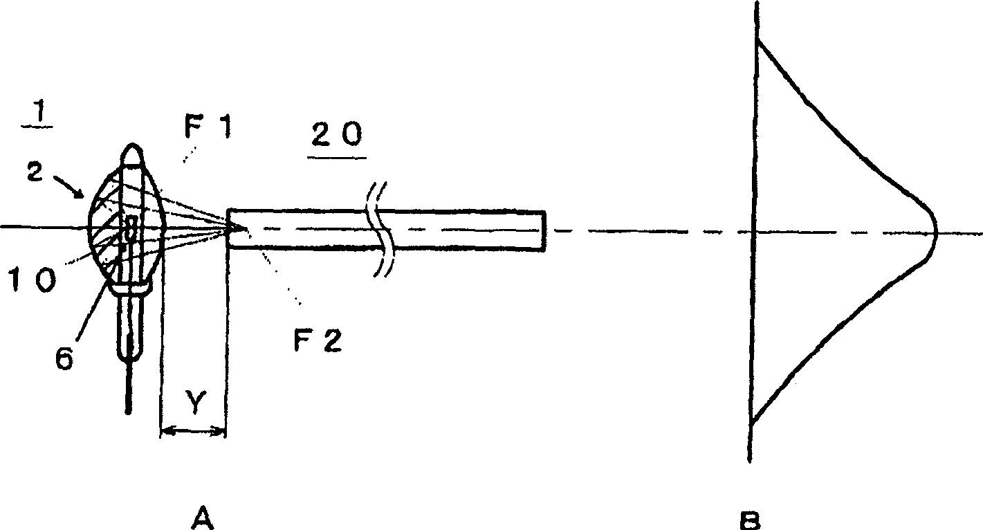
An electric lamp (1) according to the present invention is so constructed that it comprises a bulb (2) comprising a first curved face (10), the first curved face having a substantially ellipsoidal shape in cross section with a first focal point (F1) and a second focal point (F2), and being convex outwardly, and a filament (6) comprising a coil part (16) formed by winding a wire and generating a light by being energized, the filament being so arranged that the coil part (16) is positioned in an inner space (5) of the bulb (2), wherein a reflective coating is formed on the whole of outer surface or the whole of inner surface of the first curved face (10), and wherein the first curved face (10) is so adapted that the first focal point (F1) is positioned at the coil part (16), and the second focal point (F2) is positioned at a light transmission medium (20) to which an emerged light generated at the coil part (16) and reflected on the first curved face (10) is provided.

Description

technical field [0001] The present invention relates to an electric lamp of the incandescent type including a halogen lamp and the like, and more particularly to an electric lamp used as a light source for an optical fiber lighting system. Background technique [0002] In general, fiber optic lighting systems are widely used on the one hand for illuminating areas close to the hands of workers doing elaborate work in factories and for decorative lighting of showcases, on the other hand they are widely used in endoscopes, scanners, etc. , photo amplifiers, photopolymerizers, etc. required exposure. [0003] Figure 7 An example of a fiber optic lighting system is schematically shown in which a conventional halogen lamp is used as a light source, A shows the spatial relationship between the halogen lamp and the fiber, and B shows the light distribution of the exit light emitted from the fiber. exist Figure 7 In, reference numeral 100 denotes a halogen lamp, and 200 denotes an...

Claims


Application Information

Patent Timeline
Patent Type & Authority Applications(China)
IPC IPC(8): H01K7/02H01K1/32F21Y101/00H01K1/28H01K1/30
CPCH01K1/325H01K1/30H01K7/02H01K1/28
Inventor 黑泽明
Owner KAHOKU LIGHTING SOLUTIONS CORP
Learn More