Disk clamping device
A technology of clamping device and clamping rod, which is applied in the field of disk clamping device, can solve the problems of insufficient reliability of loading device and low performance of disk clamping device, and achieve the effect of stable pressing force and low cost
- Summary
- Abstract
- Description
- Claims
- Application Information
AI Technical Summary
Problems solved by technology
Method used
Image
Examples
no. 1 Embodiment
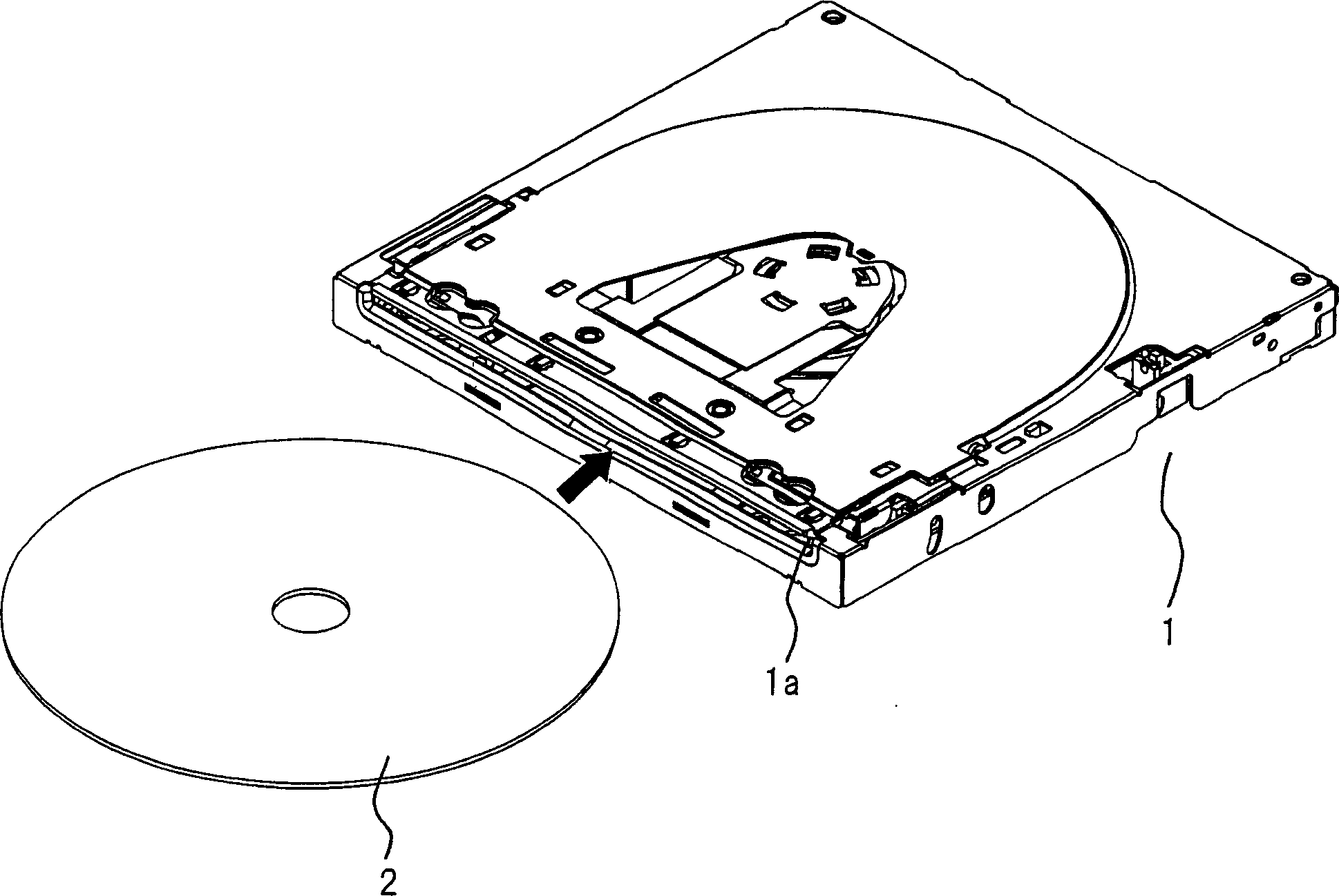
[0041] Reference Figure 1~Figure 8 A description will be given of a loading device provided with the disk clamping device according to the first embodiment of the present invention. figure 1 This is a diagram showing the outline of the structure of the loading device of the slotting method in the present embodiment. figure 1 In the loading device 1, when the disk 2 is inserted from the disk insertion port 1a, a part of the inserted disk 2 is clamped and loaded into the device, so that the disk 2 is seated on the turntable inside the loading device 1. Set location.
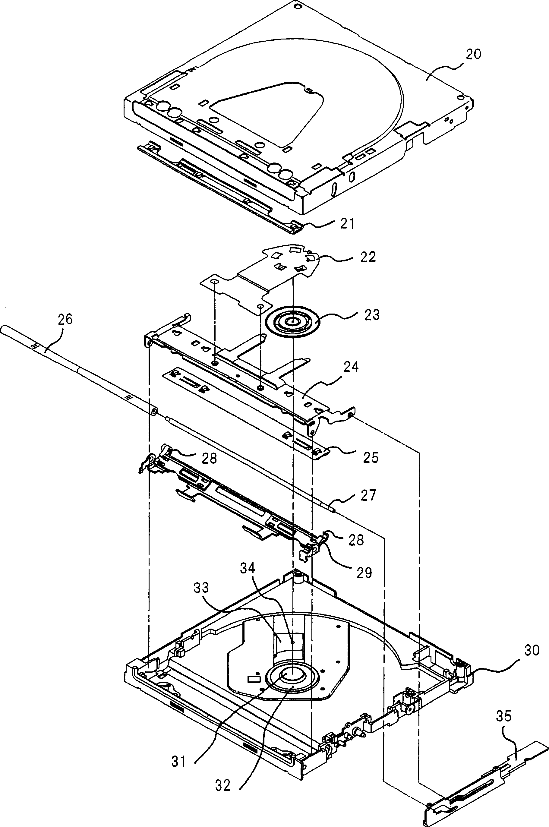
[0042] figure 2 Means figure 1 An exploded perspective view of the loading device 1 in.
[0043] Disk insertion port 1a ( figure 1 ), formed by the base plate 20 and the mechanical base plate 30. The disk guide 21 is fixed near the disk insertion port 1a of the base disk 20.
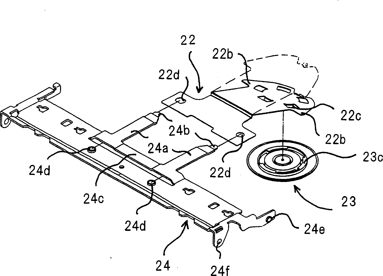
[0044] The leaf spring 22 is fixed in the clamping rod 24 on one side. The clamp 23 is supported by the back of the leaf spring 22 to rot...
no. 2 Embodiment
[0073] Reference Figure 9~Figure 11 A description will be given of a loading device equipped with a disk clamping device in the second embodiment of the present invention. Picture 9 This is a schematic overview diagram showing the structure of the loading device of the slotting method of this embodiment. Picture 9 In the loading device 100 of this embodiment, when the disk 2 is inserted from the disk insertion port 100a, a part of the inserted disk is held and loaded into the device, so that the disk 2 is seated on the turntable inside the loading device 100. Set location.
[0074] Picture 10 Means Picture 9 An exploded perspective view of the loading device 100 in. Picture 10 In the case of having a leaf spring 22' instead of the leaf spring 22, having a magnet 101 below the clamp 23, and having a suction plate 102 above the centering member 31, and figure 2 The loading device 1 of the first embodiment shown is different. In other respects, it is the same as the loading dev...
PUM
 Abstract
Description
Claims
Application Information
 - R&D
- Intellectual Property
- Life Sciences
- Materials
- Tech Scout
- Unparalleled Data Quality
- Higher Quality Content
- 60% Fewer Hallucinations
Browse by: Latest US Patents, China's latest patents, Technical Efficacy Thesaurus, Application Domain, Technology Topic, Popular Technical Reports.
© 2025 PatSnap. All rights reserved.Legal|Privacy policy|Modern Slavery Act Transparency Statement|Sitemap|About US| Contact US: help@patsnap.com


