
Network resource management device

A resource management and device management technology, applied in the field of resource management devices, can solve the problems of heavy processing load, low robustness, impossible resource management, etc.

Inactive Publication Date: 2006-10-04
PANASONIC CORP
View PDF0 Cites 0 Cited by
  • Summary
  • Abstract
  • Description
  • Claims
  • Application Information

AI Technical Summary

Problems solved by technology

When a resource management device stops operating for some reason, it becomes completely impossible to manage resources, which reveals a low robustness in the management of this resource management system
In addition, since a single resource management device handles resource reservations of all communication devices, the processing load of each resource management device is heavy

Method used


Image

  • Network resource management device
  • Network resource management device
  • Network resource management device

Examples


Embodiment Construction

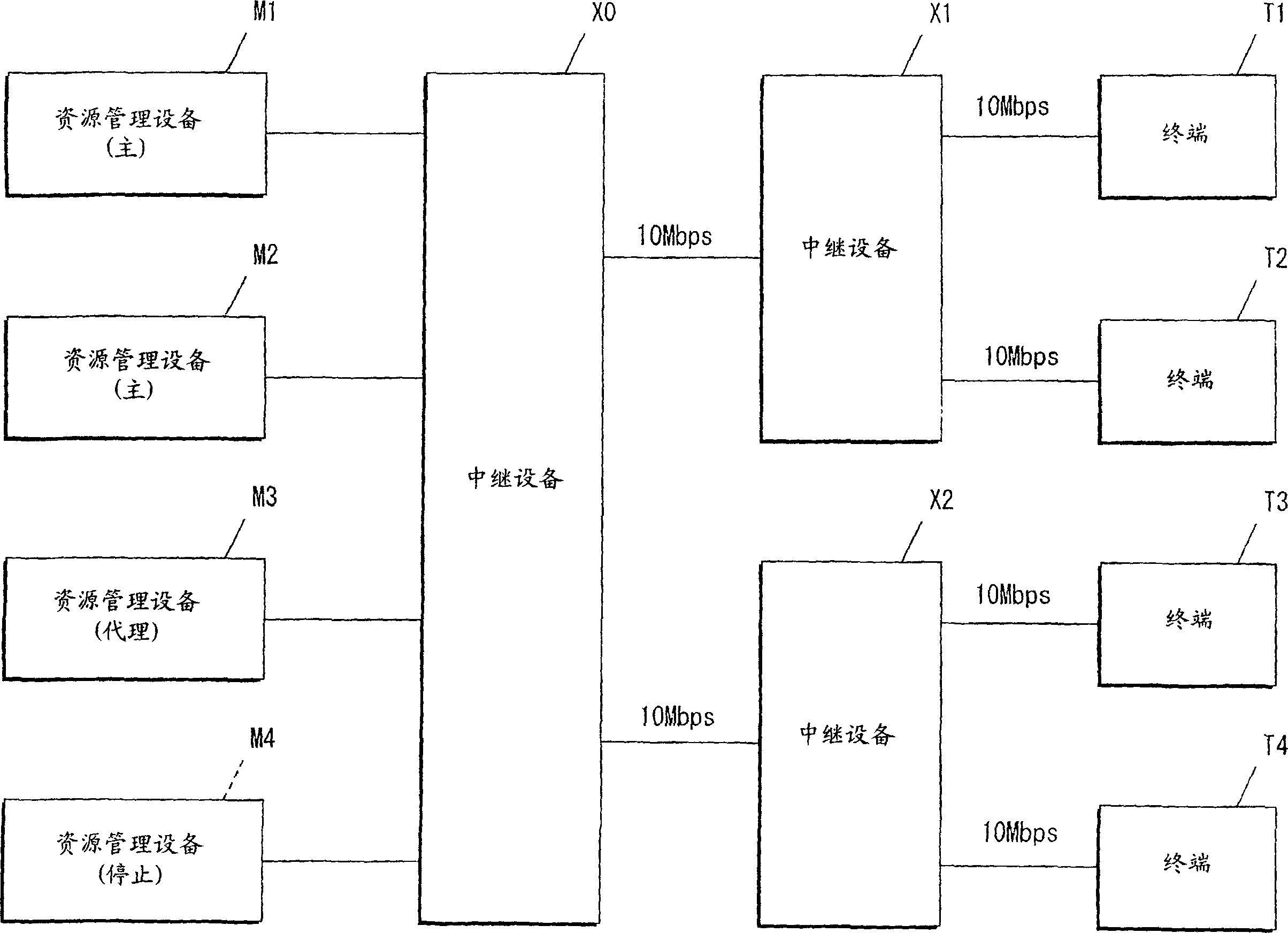
[0035] Hereinafter, embodiments of the present invention are described with reference to the drawings. figure 1 is a diagram illustrating a network configuration using a resource management device according to an embodiment of the present invention. figure 1 The initial state is illustrated.

[0036] In the current embodiment, communication bandwidth is used as a resource. In addition to the communication bandwidth, each value necessary at the time of packet relay, such as processing delay time in the relay device, variation in processing delay time, amount of memory required for relay, and CPU processing amount, etc. Available as a resource.

[0037] figure 1 The illustrated packet communication system includes four terminals T1 to T4, three relay devices X0 to X2, and four resource management devices M1 to M4. The terminals T1 to T4 work either as transmitters sending packets or as receivers receiving packets. To simplify the following description, it is assumed that...


PUM


Abstract

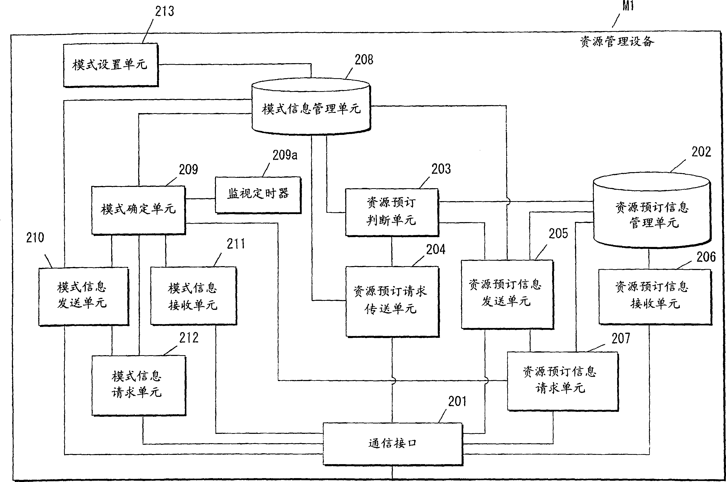
The present invention introduces a plurality of resource management devices (M1)-(M4). Each resource management device comprises a resource reservation information transmitting unit (205) and a resource reservation information receiving unit (206). Thus, even when one of the resource management devices is inactivated, the resource management can be continued. Since reserved resource information is shared among a plurality of resource management devices, if exist, the resource management can be performed without contradiction. Processing load can be decentralized by processing a resource reservation request by the plurality of resource management devices.

Description

technical field [0001] The present invention relates to a resource management device for managing a communication network, such as a packet switched network. Background technique [0002] Document 1 (RFC2816 "A Framework for Integrated Services Over Shared and Switched IEEE 802 LAN Technologies" of IETF, May 2000) discloses a technique for managing resources such as communication bandwidth in a packet-switched network. [0003] Figure 9 It is a diagram illustrating a network structure using a conventional resource management device. exist Figure 9 In , relay devices X0 to X2 constitute a communication network. The terminals T1 and T2 are connected to the communication network via the relay device X1, and the terminals T3 and T4 are connected to the communication network via the relay device X2. The resource management device M9 is connected to the communication network via the relay device X0. The terminals T1 to T4 can communicate with each other via a communication ne...

Claims


Application Information

Patent Timeline
Patent Type & Authority Applications(China)
IPC IPC(8): G06F11/20H04L12/56H04L12/24
CPCH04L47/822H04L43/0811H04L12/5695H04L47/724H04L47/782H04L47/15H04L47/125H04L2012/5627H04L47/70
Inventor 大浦正登安藤智川口雄一大元政雄
Owner PANASONIC CORP
Learn More