Eureka AIR delivers breakthrough ideas for toughest innovation challenges, trusted by R&D personnel around the world.

Vehicle seat

A vehicle seat and seat seat technology, which is applied to vehicle seats, vehicle parts, special positions of vehicles, etc., can solve the problems of high cost and complex structure of supporting components, and achieve the effect of easy adjustment and comfortable ride

Active Publication Date: 2006-10-18
GRAMMER AG
View PDF3 Cites 17 Cited by
  • Summary
  • Abstract
  • Description
  • Claims
  • Application Information

AI Technical Summary

Problems solved by technology

[0004] This support structure is complex and costly, requiring a device to position the support member, sliding parts, and multiple horizontally extending and interconnected support arms

Method used


Image

  • Vehicle seat
  • Vehicle seat
  • Vehicle seat

Examples


Embodiment Construction

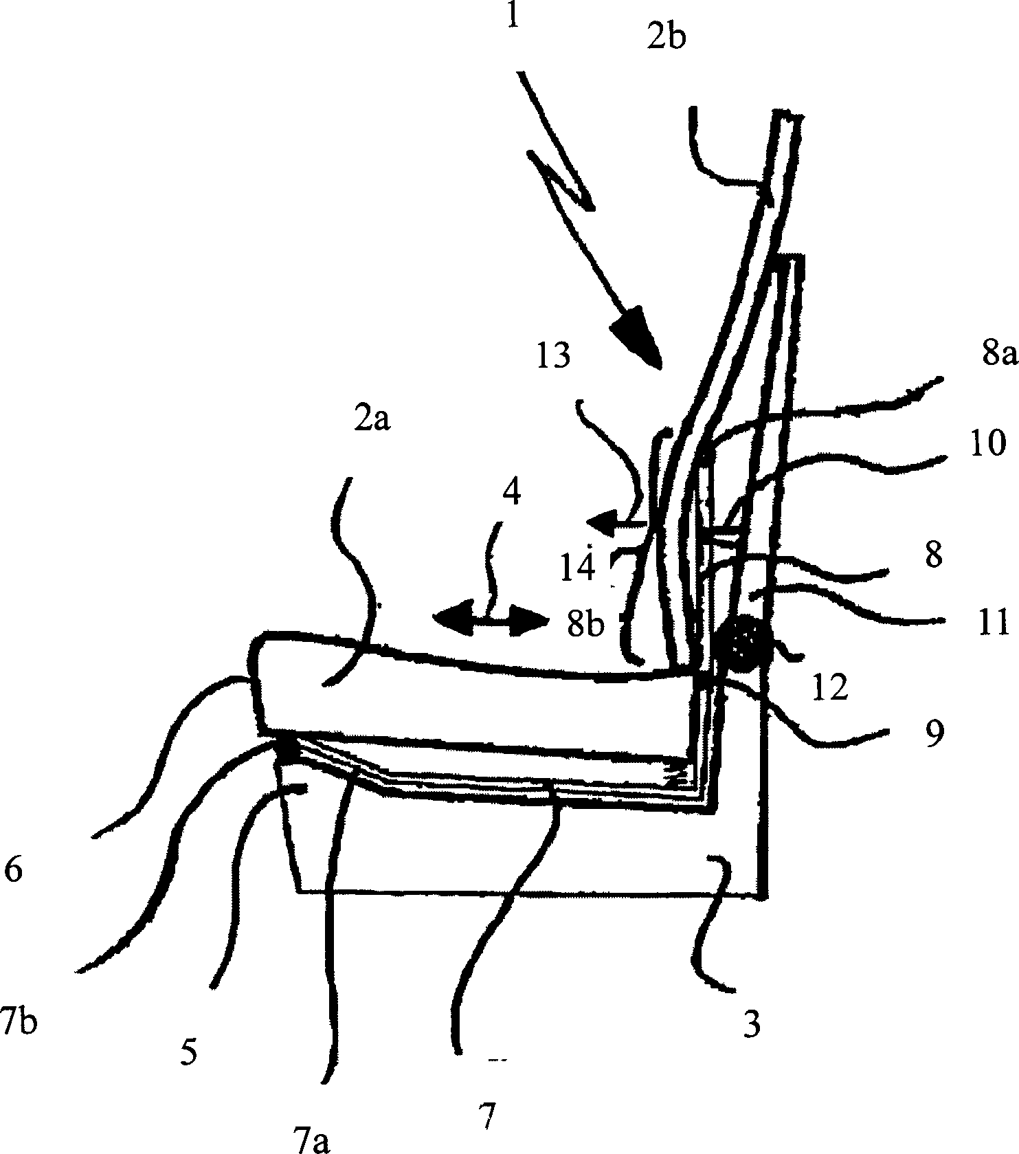
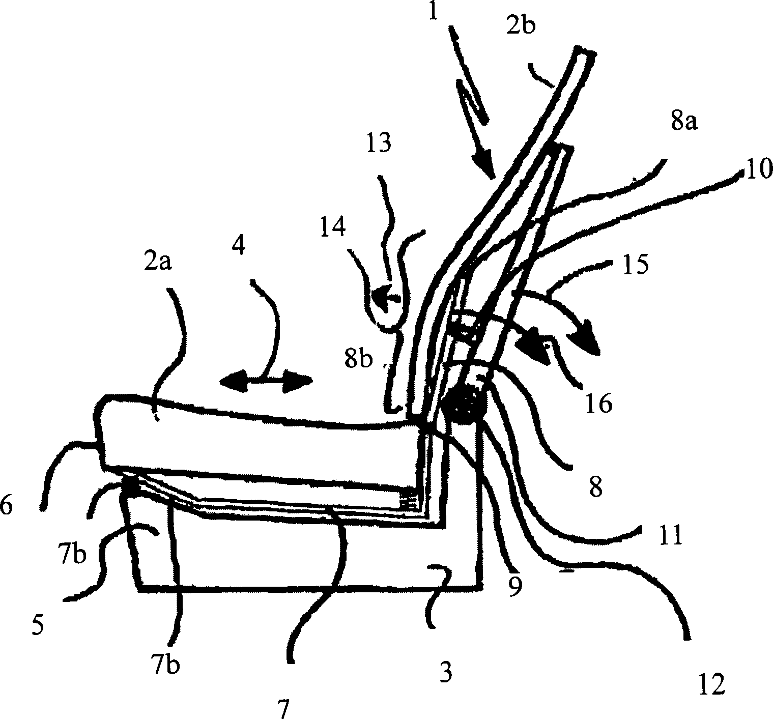
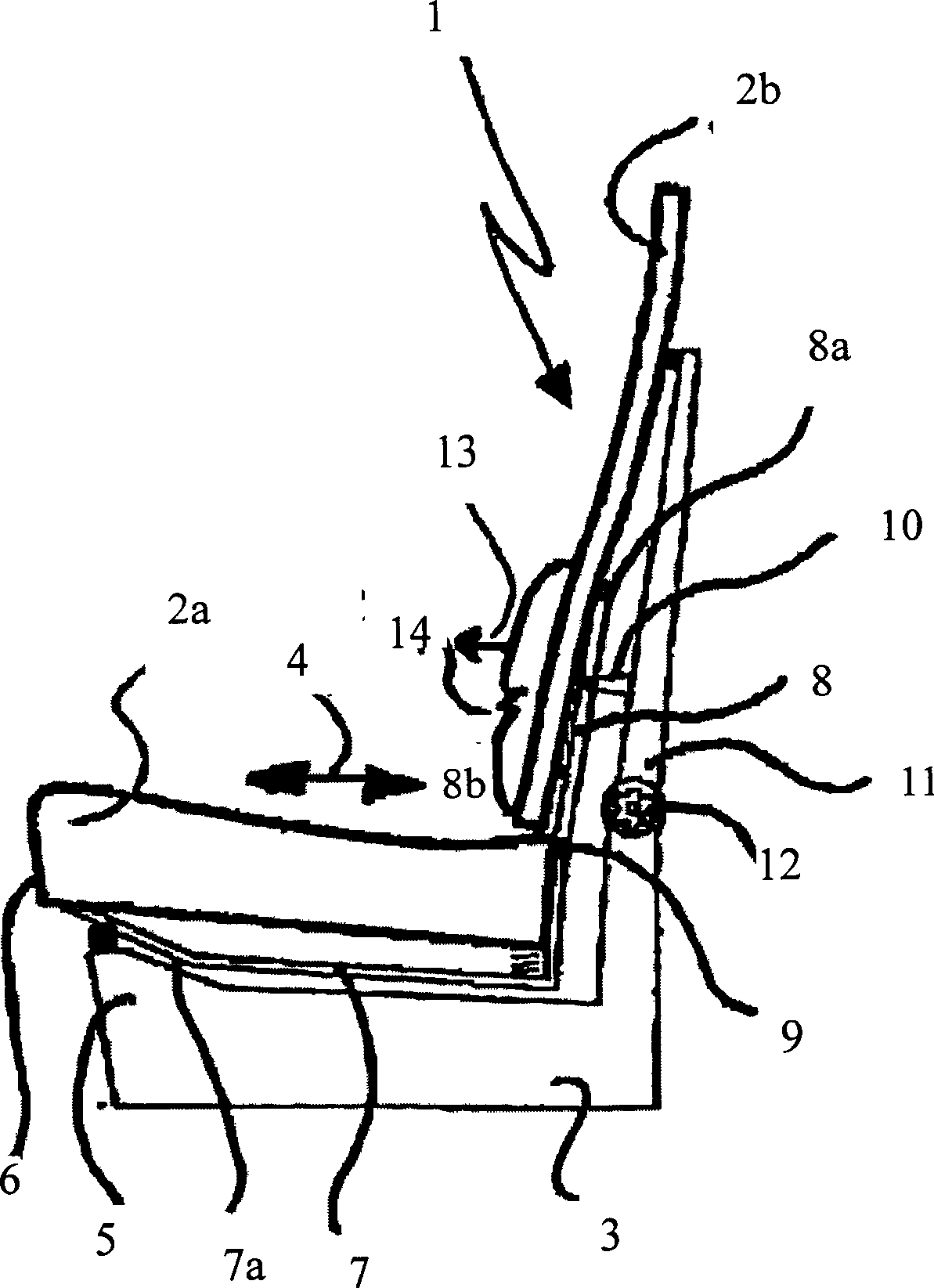
[0029] figure 1 The vehicle seat shown has a backrest 1 and a seat seat 2a, wherein the backrest is provided with a back cushion 2b. Both the seat 2 a and the back pad 2 b are mounted on the base frame 3 .

[0030] By means of the sliding bearing system 7, 7a, the seat 2a can be moved forwards and backwards.

[0031] Since the front portion of the base frame 3 is designed to protrude upwards, the portion 6 of the seat 2a facing the front of the vehicle automatically rises during the forward movement. As a result, the sliding bearing parts 7a mounted at an oblique angle to the seat surface and designed as rails roll on the rollers 7b, lifting the part 6 of the seat 2a towards the front of the vehicle.

[0032] The upper end 8a of the rocker-shaped part 8 pushes the backrest pad 2b to be spaced a fixed distance from the rotatable part 11 of the base frame 3 by the action of the spacer 10 .

[0033] For rotational movement, the rocker-shaped part 8 has at its bottom end a rot...


PUM


Abstract

The seat has a back rest (1) and a seat part. The seat part is shiftable against a base frame in a forward and rearward direction. The back rest comprises a deformable lumbar vertebra region (14) and a jack shaped unit extends along a longitudinal direction of the back rest. A rotatable section of the jack shaped unit is fastened to a back rest region of the base frame, where the jack shaped unit is connected with S-shaped rods.

Description

technical field [0001] The invention relates to a vehicle seat with a backrest and a seat, wherein the seat is movable forwards and rearwards relative to a base frame, and the backrest has a lumbar region deformable in the fore-and-aft direction. Background technique [0002] European patent 0957716B1 discloses a vehicle seat with a backrest and a seat seat, wherein a lumbar support structure is installed in the backrest area, and the lumbar support mechanism is composed of flexible support units fastened at its upper and lower ends and combined together so that An arch is formed in the lumbar spine region of the backrest. In this way, the lumbar support that can be adjusted forward can be formed by relying on the convex deformation of the backrest in the lumbar spine area, and in order to improve the riding comfort, different supports are provided according to the size of the gap between the back of the human body and the backrest. [0003] The deformation of the lumbar su...

Claims


Application Information

Patent Timeline
Patent Type & Authority Applications(China)
IPC IPC(8): B60N2/66
CPCB60N2/2209B60N2/643B60N2/66
Inventor 约瑟夫·科尔克里斯汀·埃克尔
Owner GRAMMER AG
Why Eureka
Eureka Blog
Learn More