Supercharge Your Innovation With Domain-Expert AI Agents!

Propeller

A technology of propellers and impellers, which is applied in the direction of machines/engines, mechanical gear transmissions, non-variable pumps, etc. It can solve the problems of large installation space, reducing the area where water can pass backwards, and occupation.

Inactive Publication Date: 2006-10-18
陈 学毅
View PDF0 Cites 2 Cited by
  • Summary
  • Abstract
  • Description
  • Claims
  • Application Information

AI Technical Summary

Problems solved by technology

[0004] Although the above-mentioned propeller 1 can drive the water flow to generate flow, the blades 12 used to disturb the water flow to generate flow are located around, and the central part surrounded by the blade 12 is occupied by the mandrel 11, so there will be no There is water flow through, so the area that the water flow can pass backward is reduced, the flow flux is reduced, and the propulsion efficiency is poor.
In addition, one motor 13 can only drive one spindle 11 and the blades 12 installed on it, so if more propulsion power is needed, multiple propellers 1 must be installed on the implement, and multiple motors 13 must be driven. In addition to taking up a large installation space, it also consumes power energy, so the structure of the thruster 1 still needs to be improved

Method used


Image

  • Propeller
  • Propeller
  • Propeller

Examples


Embodiment Construction

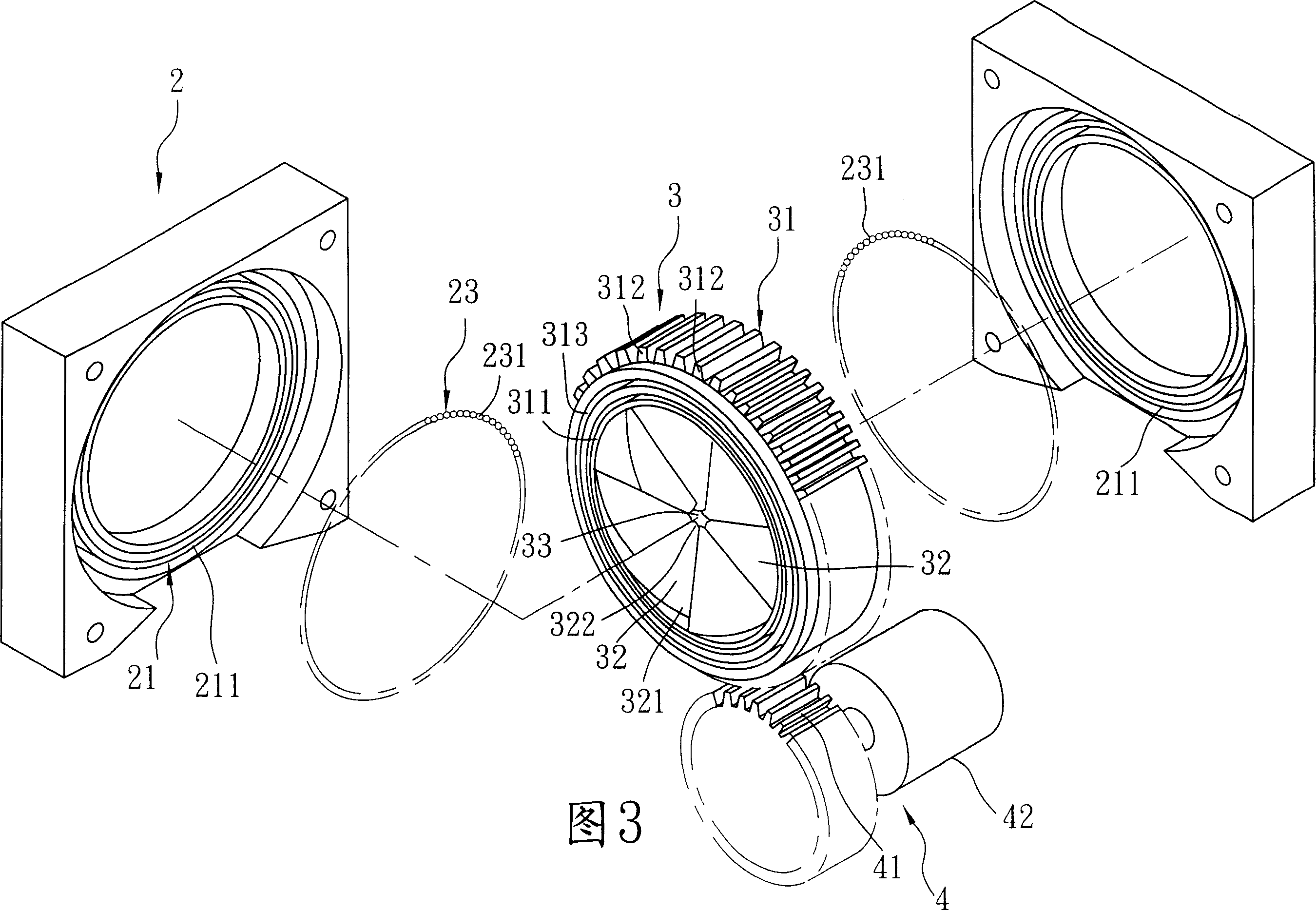
[0017] See Figure 3, Figure 4 and Figure 5 , is a preferred embodiment of the propeller of the present invention, including: a fixing device 2 , an impeller device 3 , and a driving device 4 .

[0018] The fixing device 2 has an annular fixing seat 21, an annular receiving groove 22 formed in the fixing seat 21 and opening radially toward the center (see Figure 7 ), and a pivot member 23 rotatably installed in the receiving groove 22. The fixing base 21 has two sidewalls 211 that are fastened together front and rear and cooperate to define the receiving groove 22 . The pivotal member 23 has a plurality of balls 231 that surround twice and are installed in the receiving groove 22 . Of course, in terms of design, the pivotal member 23 can also be a bearing.

[0019] The impeller device 3 is rotatably pivoted on the fixing device 2, and has a hollow ring-shaped orbiting seat 31, blades extending radially toward the center from an inner peripheral surface of the orbiting sea...


PUM


Abstract

The propeller includes one fixture, one rotating vane wheel unit fixed onto the fixture, and one drive unit beside the vane wheel unit. The vane wheel unit has one hollow ring seat, vanes bending towards the center and intermittently arranged inside the ring seat, and one flow space limited with the vanes in the center of the ring seat. The drive unit rotates the ring seat together with the vanes, so that water flow passes through the flow space from front to back. The present invention has increased backward water flow area and excellent driving effect.

Description

technical field [0001] The invention relates to a propeller, in particular to a propeller installed in ships and other implements. Background technique [0002] Generally, propellers act on water to propel ships and other equipment forward, and the result of the propeller driving the water flow will affect the driving efficiency of the equipment. Therefore, the propeller structure is an important part that needs to be developed and improved by all related industries. [0003] refer to figure 1 and figure 2 , a kind of propeller 1 in the past is installed in steamer 9 both sides, and comprises: a mandrel 11, a plurality of blades 12 that are installed on mandrel 11 periphery at intervals, and a motor 13 that is installed on mandrel 11 rears. When the motor 13 drives the spindle 11 to rotate, it will rotate together with the vanes 12 to drive the fluid to flow through the vanes 12 from front to back. [0004] Although the above-mentioned propeller 1 can drive the water flo...

Claims


Application Information

Patent Timeline
Patent Type & Authority Applications(China)
IPC IPC(8): B63H23/02F04D13/00F04D25/00
Inventor 陈学毅
Owner 陈 学毅
Features
  • R&D
  • Intellectual Property
  • Life Sciences
  • Materials
  • Tech Scout
  • Unparalleled Data Quality
  • Higher Quality Content
  • 60% Fewer Hallucinations
Learn More