Supercharge Your Innovation With Domain-Expert AI Agents!

Driving circuit for the LED charge pump

A technology of light-emitting diodes and driving circuits, which is applied to the layout of electric lamp circuits, light sources, electric light sources, etc., and can solve the problems of too large, unable to achieve driving efficiency, and unable to effectively control the brightness of light-emitting diodes, etc.

Inactive Publication Date: 2007-07-11
GLOBAL MIXED MODE TECH
View PDF0 Cites 15 Cited by
  • Summary
  • Abstract
  • Description
  • Claims
  • Application Information

AI Technical Summary

Problems solved by technology

[0005] Although the known charge pump driving circuit 10 shown in FIG. 1(a) can provide a stably regulated driving voltage V out to the load 11, but in the case of the load 11 belonging to a light emitting diode (LED), the known charge pump drive circuit 10 cannot effectively control the brightness of the light emitting diode, because the brightness of the light emitting diode is determined by the driving current rather than the driving voltage
Moreover, in order to ensure that the LED is turned on, the known charge pump driving circuit 10 usually provides an unnecessarily large driving voltage V out , resulting in the inability to achieve the best driving efficiency

Method used


Image

  • Driving circuit for the LED charge pump
  • Driving circuit for the LED charge pump
  • Driving circuit for the LED charge pump

Examples


Embodiment Construction

[0044] The foregoing and other objects, features, and advantages of the present invention will be more apparent from the following description and accompanying drawings. Here, preferred embodiments according to the present invention will be described in detail with reference to the accompanying drawings.

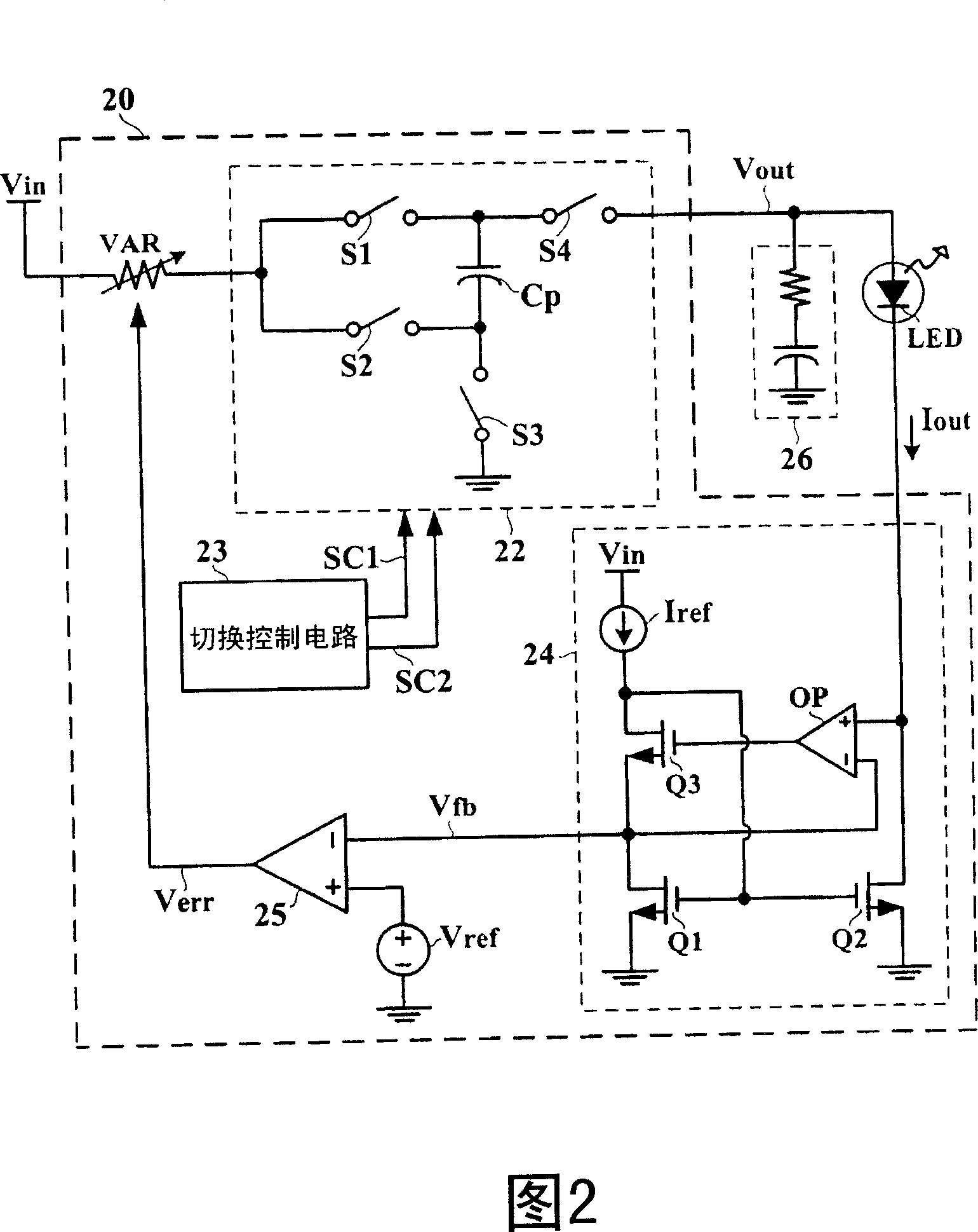
[0045] FIG. 2 shows a charge pump driving circuit 20 according to a first embodiment of the present invention for converting an input voltage source V in becomes a driving voltage V out , and provide a regulated drive current I out , thus driving a light-emitting diode LED. The charge pump driving circuit 20 of the first embodiment mainly includes a charge pump 22 , a switching control circuit 23 , a current regulating circuit 24 , an error amplifier 25 , and a variable resistance unit VAR.

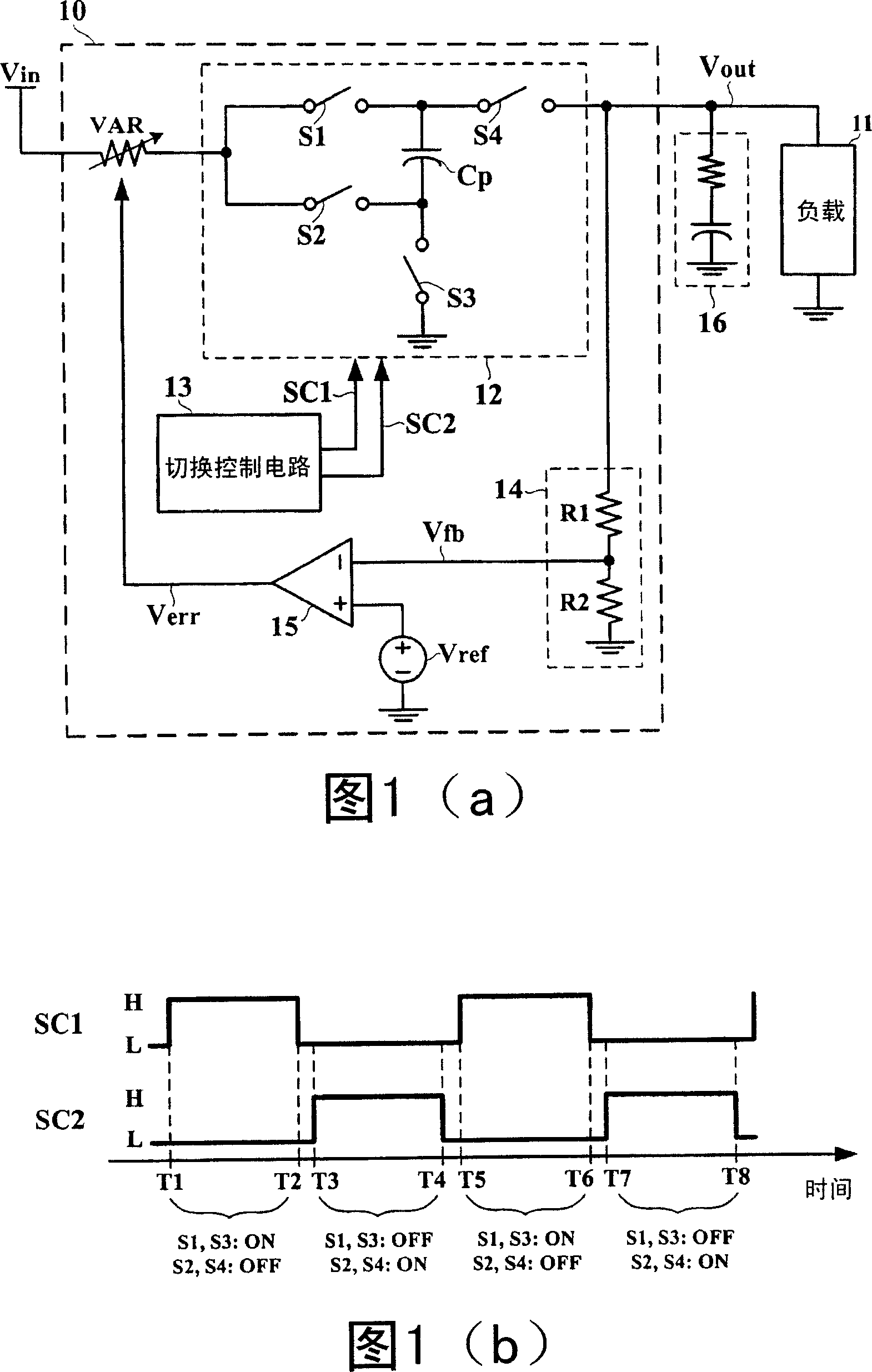
[0046] The charge pump 22 shown in FIG. 2 is implemented by a 2x charge pump. Its circuit composition and operation method are substantially the same as the 2x charge pump 12 shown i...


PUM


Abstract

This invention relates to one method to alternate charge phase and discharge phase with charge pump into input voltage source as drive voltage to supply the light diode, wherein, current set unit determines one reference current; the current adjust unit has current adjust terminal and feedback test end; the current adjust terminal is coupled to light diode to control current in proportion to reference current through light diode; the feedback test end provides feedback signals for one current adjust characteristic voltage.

Description

technical field [0001] The invention relates to a charge pump driving circuit, in particular to a charge pump driving circuit for light emitting diodes. Background technique [0002] FIG. 1( a ) shows a detailed circuit diagram of a known charge pump driving circuit 10 . The charge pump driving circuit 10 converts an input voltage source V in becomes a driving voltage V out , for driving a load 11 . Many times the input voltage source V in may not be suitable for direct use to drive a load11, such as an input voltage source V in When situations such as too high, too low, or too large a disturbance occur, it is necessary to use the charge pump drive circuit 10 to adjust an appropriate and stable drive voltage V out . For example, the known charge pump driving circuit 10 shown in FIG. phase and a discharge phase, resulting in a drive voltage V out equal to the input voltage source V in twice as much. [0003] Specifically, the 2x charge pump 12 shown in FIG. 1( a ) i...

Claims


Application Information

Patent Timeline
IPC IPC(8): H05B37/00H05B37/02H02M3/07G05F1/46
Inventor 陈天赐岑嘉宏
Owner GLOBAL MIXED MODE TECH
Features
  • R&D
  • Intellectual Property
  • Life Sciences
  • Materials
  • Tech Scout
  • Unparalleled Data Quality
  • Higher Quality Content
  • 60% Fewer Hallucinations
Learn More