Optical element driving mechanism

A technology of optical components and driving mechanisms, applied in the direction of optical components, optical, electrical components, etc., can solve problems such as unsatisfactory, and achieve the effects of reduced occupied area, better driving efficiency, and reduced size

Pending Publication Date: 2020-12-15
TDK TAIWAN
View PDF14 Cites 4 Cited by
  • Summary
  • Abstract
  • Description
  • Claims
  • Application Information

AI Technical Summary

Problems solved by technology

However, although the existing drive mechanism can achieve the aforementioned camera or video functions, it still cannot meet all demands

Method used


Image

  • Optical element driving mechanism
  • Optical element driving mechanism
  • Optical element driving mechanism

Examples


Embodiment Construction

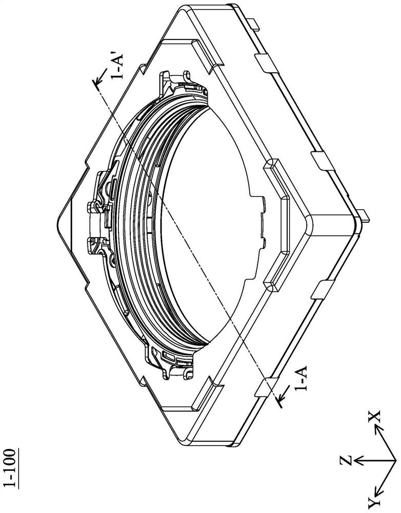
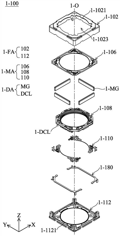
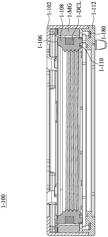
[0338] In order to make the purpose, features and advantages of the present disclosure more comprehensible, the following specific embodiments are described in detail with accompanying figures. Wherein, the configuration of each element in the embodiment is for illustration, not to limit the present disclosure. Moreover, part of the reference numerals in the embodiments is repeated, for the sake of simplicity of description, it does not imply the correlation between different embodiments. The directional terms mentioned in the following embodiments, such as: up, down, left, right, front or back, etc., are only directions referring to the attached drawings. Accordingly, the directional terms used are for illustration and not for limitation of the present disclosure.

[0339] In addition, relative terms such as "lower" or "bottom" and "higher" or "top" may be used in the embodiments to describe the relative relationship of one element to another element in the drawings. It wil...


PUM


Abstract

An optical element driving mechanism is provided and includes a fixed assembly, a movable assembly, and a driving assembly. The movable assembly is configured to be connected to an optical element. The movable assembly is movable relative to the fixed assembly. The optical element has an optical axis. The driving assembly is configured to drive the movable member to move relative to the fixed assembly.

Description

technical field [0001] The present disclosure relates to an optical element driving mechanism, in particular to an optical element driving mechanism with a flat coil. Background technique [0002] With the development of technology, many electronic devices (such as smart phones) now have the function of taking photos or recording videos. Through the camera module installed on the electronic device, the user can operate the electronic device to capture various photos. [0003] The design of today's electronic devices is constantly developing toward the trend of miniaturization, so that various components or structures of the camera module must also be continuously reduced to achieve the purpose of miniaturization. Generally speaking, the driving mechanism in the camera module may have a lens carrier configured to carry a lens, and the driving mechanism may have the function of auto focusing or optical image stabilization. However, although the existing driving mechanism can...

Claims


Application Information

Patent Timeline
Patent Type & Authority Applications(China)
IPC IPC(8): G02B7/09G03B13/36G03B5/00H04N5/232
CPCG02B7/09G03B13/36G03B5/00H04N23/687G02B7/08H01F7/066H01F5/04G02B27/646H04N23/55H04N23/57
Inventor 胡朝彰何亮廷徐辰二詹益良曾福来吴富源郭侲圻王英任夏伟瀚曾怡歆
Owner TDK TAIWAN
Why Eureka
Try Eureka