Dual-handle dual-function constant temperature valve core

A thermostatic valve core, dual-function technology, applied in the valve core field, can solve the problem that a single function must be combined with other valve cores, etc., to achieve the effect of safe and reliable operation and stable outlet water temperature

Active Publication Date: 2006-10-25
谢庆俊
View PDF1 Cites 13 Cited by
  • Summary
  • Abstract
  • Description
  • Claims
  • Application Information

AI Technical Summary

Problems solved by technology

[0005] As mentioned above, the present invention scientifically integrates the constant temperature function and the flow control function on one spool, which overcomes the defect that the conventional thermostatic spool

Method used


Image

  • Dual-handle dual-function constant temperature valve core
  • Dual-handle dual-function constant temperature valve core
  • Dual-handle dual-function constant temperature valve core

Examples


Example Embodiment

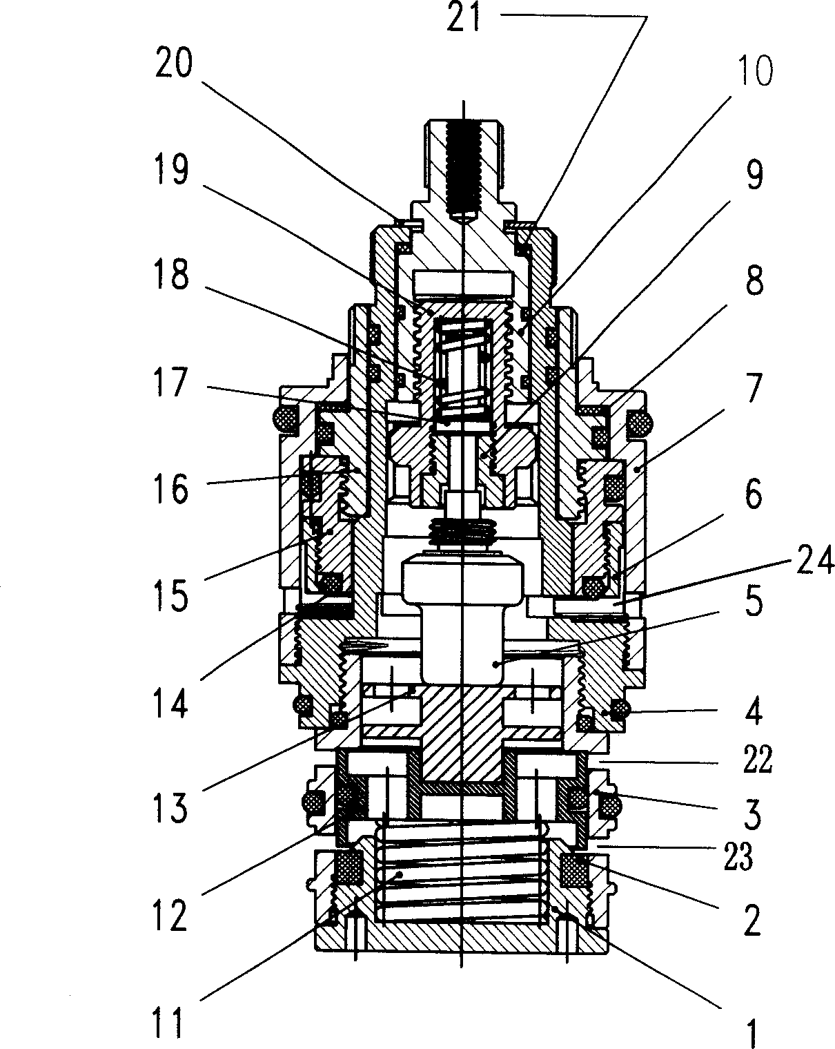
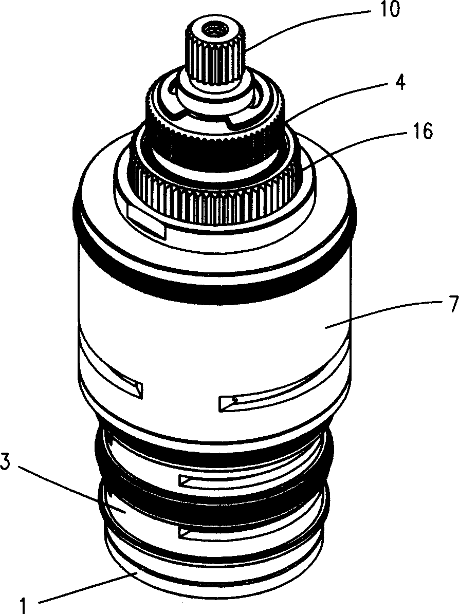
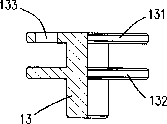
[0012] like figure 1 As shown, the double-handle dual-function valve core of the present invention includes a base 1, a sealing gasket 2, a thermostatic valve sleeve 3, a valve core body 4, a temperature sensor 5, a sealing ring compression nut 6, a jacket 7, a wear-resistant pad 8, and a push rod Seat body 9, thermostat valve stem 10, return spring 11, regulator 12, water mixer 13, sealing ring 14, flow regulating slide valve 15, flow regulating bolt 16, ejector rod 17, safety spring 18, collar 20 and O-rings of various specifications.

[0013] Combine below figure 1 and figure 2 Describe the details of each component and the connection relationship between components. The base 1, the thermostatic valve sleeve 3 and the valve core body 4 are sequentially connected to form a valve body together. Wherein, a gasket 2 is installed between the base 1 and the thermostatic valve sleeve 3 , the thermostatic valve sleeve 3 is provided with a cold water inlet 22 and a hot water in...


PUM


Abstract

The invention discloses double handles double functions thermo valve core. It includes valve body, back spring, adjustor, water mixer, temperature sensor, and temperature controlled package. And they are orderly set in the valve body. It also includes jacketing and flow controlled package. It has the advantages of safe, reliable, stable temperature, and simple operation.

Description

technical field [0001] The invention relates to a valve core, in particular to a dual-handle dual-function constant temperature valve core. Background technique [0002] Chinese patent authorization announcement No. 2703176 discloses a thermostatic valve core, including valve stem, collar, compression bolt, buffer spring, adjustment bolt, top cap, filter screen, regulator, thermal element, valve core body and valve core. Body; wherein, a water mixer is set on the rod of the thermal element, the water mixer is against the head of the thermal element, the return spring is set on the cylinder at the lower end of the water mixer, and the other end of the return spring is against the cylinder at the lower end of the water mixer. Lean on the inner boss of the valve body. The thermostatic spool realizes the thermostatic control function through the cooperation of buffer springs, adjusting bolts, top caps, regulators, heat-sensitive elements and other components. However, the disa...

Claims


Application Information

Patent Timeline
IPC IPC(8): F16K11/00F16K31/64
Inventor 谢庆俊
Owner 谢庆俊
Why Eureka
Try Eureka