Backlight module

A backlight module and light source technology, applied in optics, nonlinear optics, instruments, etc., can solve the problems of generating bright and dark bands, increasing costs, and insufficient lighting areas, reducing usage and avoiding the generation of bright and dark bands. , The effect of uniform and bright lighting

Active Publication Date: 2006-10-25
AU OPTRONICS CORP
View PDF0 Cites 2 Cited by
  • Summary
  • Abstract
  • Description
  • Claims
  • Application Information

AI Technical Summary

Problems solved by technology

[0003] In conventional technology, too many light sources (light emitting diodes) 12 are used, resulting in an increase in cost
However, if the width of the pitch P1 is directly increased in the traditional design to reduce the number of light sources (light emitting diodes) 12 used, some illuminated areas will not be illuminated enough, resulting in defects such as bright and dark bands

Method used


Image

  • Backlight module
  • Backlight module
  • Backlight module

Examples


Embodiment Construction

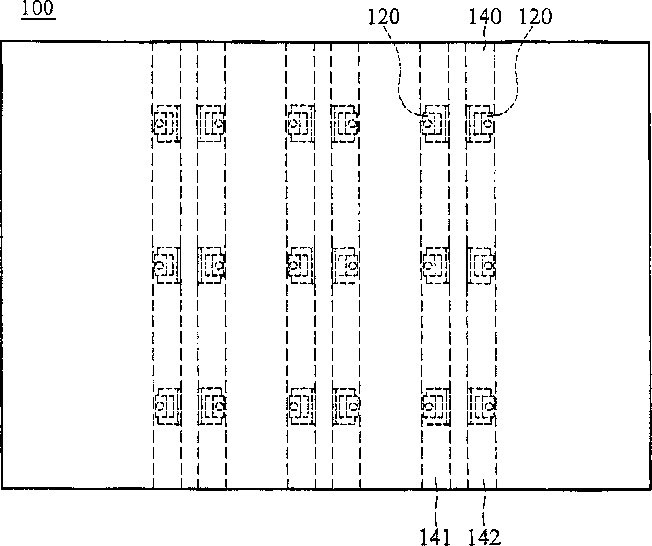
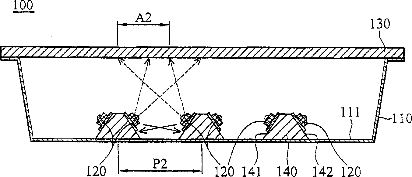
[0035] refer to Figure 2a as well as Figure 2b , which shows the backlight module 100 according to the first embodiment of the present invention, including a reflector 110 , a plurality of light sources 120 , a plate 130 and a plurality of heat conducting structures 140 . The reflective plate 110 has a reflective surface 111 . The heat conducting structure 140 is disposed on the reflective surface 111 and includes a first side 141 and a second side 142 . The light source 120 is disposed on the first side 141 and the second side 142 .

[0036] The material of the heat conducting structure 140 can be metal or ceramics. The light source 120 is a light emitting diode (LED). The board 130 can be a diffuser board or a brightening sheet.

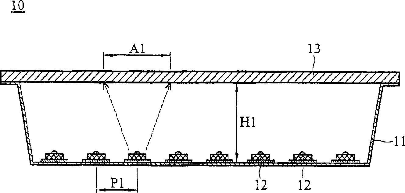
[0037] In the embodiment of the present invention, since the illumination of each illumination area (for example, illumination area A2) is provided by multiple light sources 120 at the same time, therefore, there will not be the problem that...


PUM


Abstract

The present invention includes one reflector and plurality of light sources. Said Reflector includes at least one bending portion, which includes one first side and one second side. Plurality of light sources is set on said first side and second side.

Description

technical field [0001] The present invention relates to a backlight module, in particular to a backlight module provided with a heat conduction structure. Background technique [0002] refer to figure 1 , which shows a traditional backlight module 10 using light emitting diodes (LEDs) as a light source, including a reflector 11 , a plurality of light sources 12 and a plate 13 . In the conventional technology, there is a fixed distance P1 between the light sources 12 , and a fixed height H1 between the plate 13 and the bottom surface of the reflector 11 . Since a single light source 12 is in charge of a specific illumination area A1, there needs to be a fixed ratio between the pitch P1 and the height H1. Under this fixed ratio, the backlight module 10 can provide uniform light and avoid bright and dark bands. [0003] In the conventional technology, too many light sources (light emitting diodes) 12 are used, which increases the cost. However, if the width of the pitch P1 i...

Claims


Application Information

Patent Timeline
Patent Type & Authority Applications(China)
IPC IPC(8): G02F1/1335G02F1/1333
Inventor 周信宏彭中刘仁绮
Owner AU OPTRONICS CORP
Why Eureka
Try Eureka