
Exhaust treatment diagnostic using a temperature sensor

A technology of exhaust gas treatment and sensor, which is applied in the diagnosis device of exhaust gas treatment device, exhaust gas treatment, electric control of exhaust gas treatment device, etc., can solve problems such as inappropriate amount

Inactive Publication Date: 2006-12-06
GM GLOBAL TECH OPERATIONS LLC
View PDF0 Cites 6 Cited by
  • Summary
  • Abstract
  • Description
  • Claims
  • Application Information

AI Technical Summary

Problems solved by technology

Faulty injectors or insufficient dosing agent supply sources resulting in inappropriate amounts of dosing agent for proper exhaust gas treatment

Method used


Image

  • Exhaust treatment diagnostic using a temperature sensor
  • Exhaust treatment diagnostic using a temperature sensor
  • Exhaust treatment diagnostic using a temperature sensor

Examples


Embodiment Construction

[0019] Detailed Description of Preferred Embodiments

[0020] The following description of the preferred embodiments is merely exemplary in nature and is not intended to limit the invention, its application or use. For the sake of clarity, the same reference numerals are used to designate the same parts in the figures. The term "component" as used herein means an Application Specific Integrated Circuit (ASIC), an electronic circuit, a processor (shared, dedicated or grouped) and memory executing one or more software or firmware programs, An integrated logic circuit or other suitable component that provides the stated functionality.

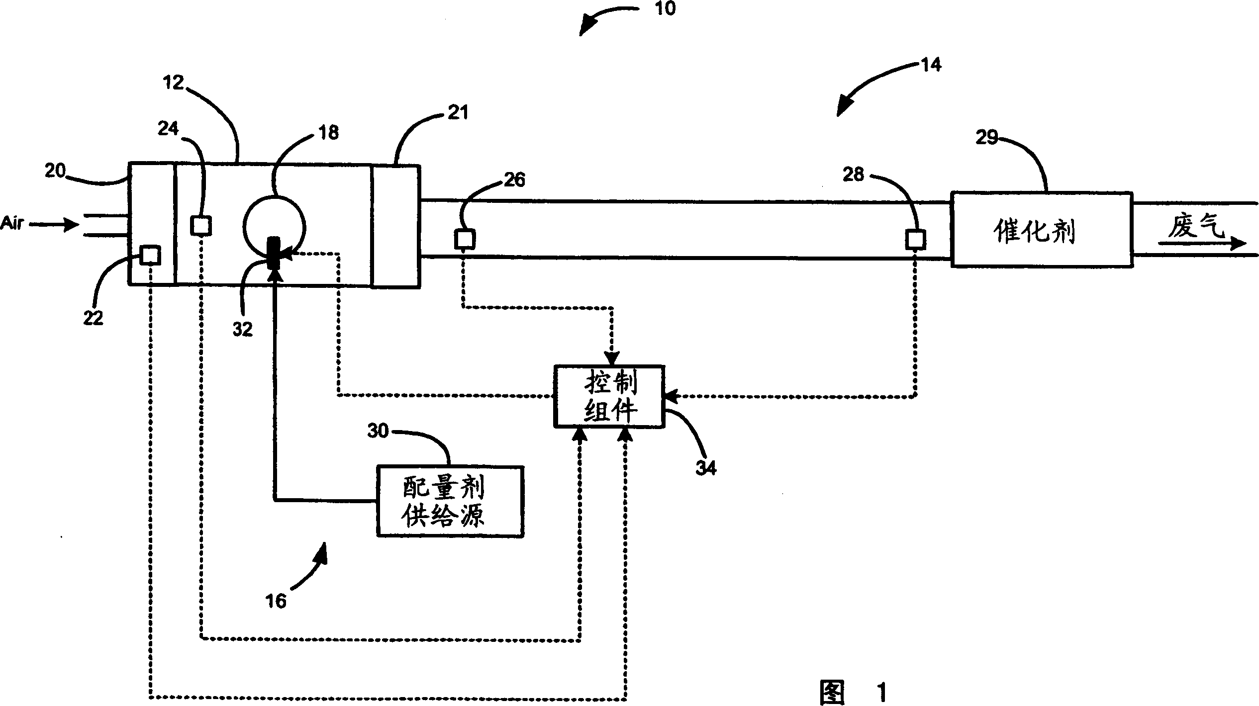
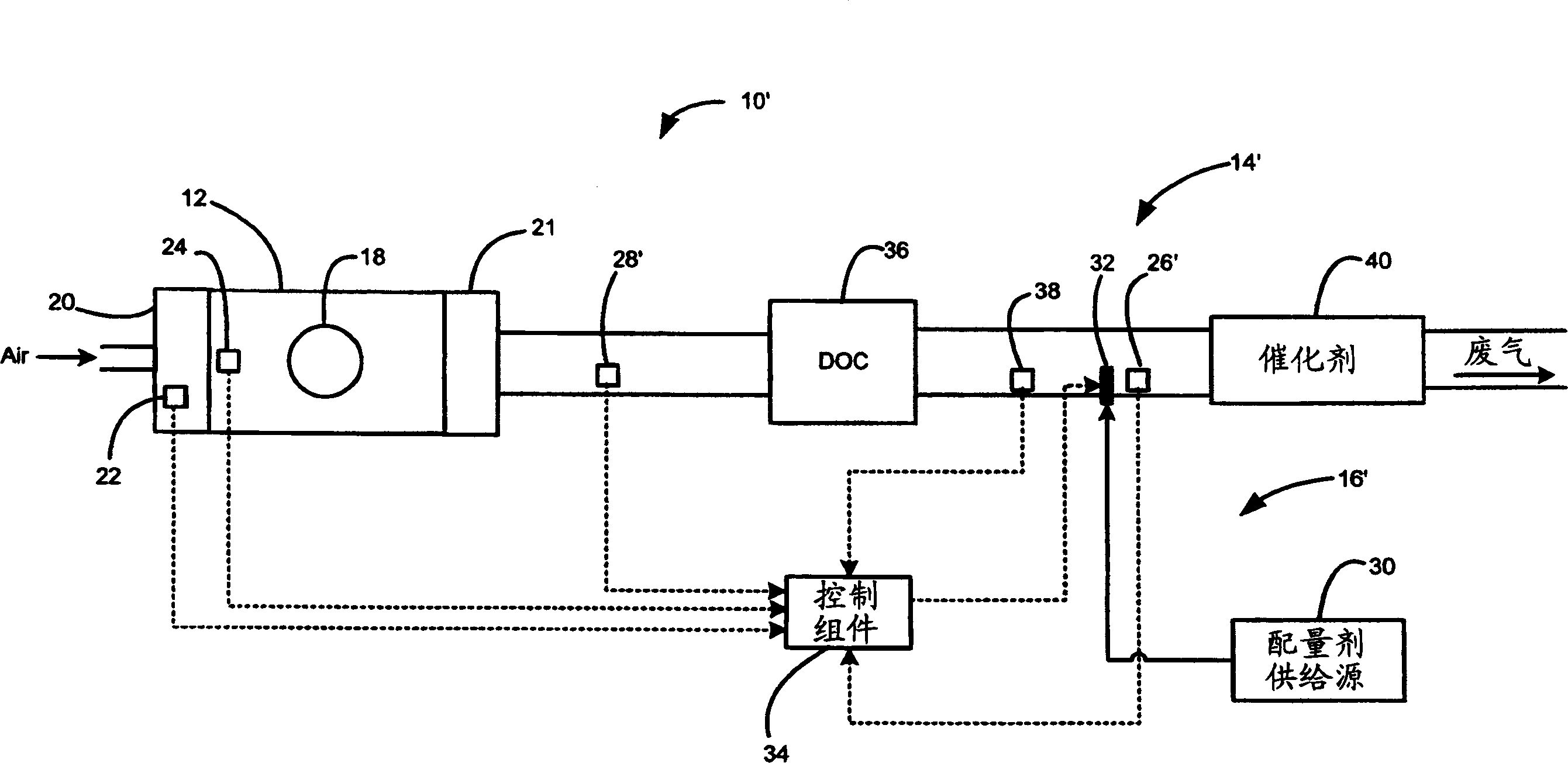
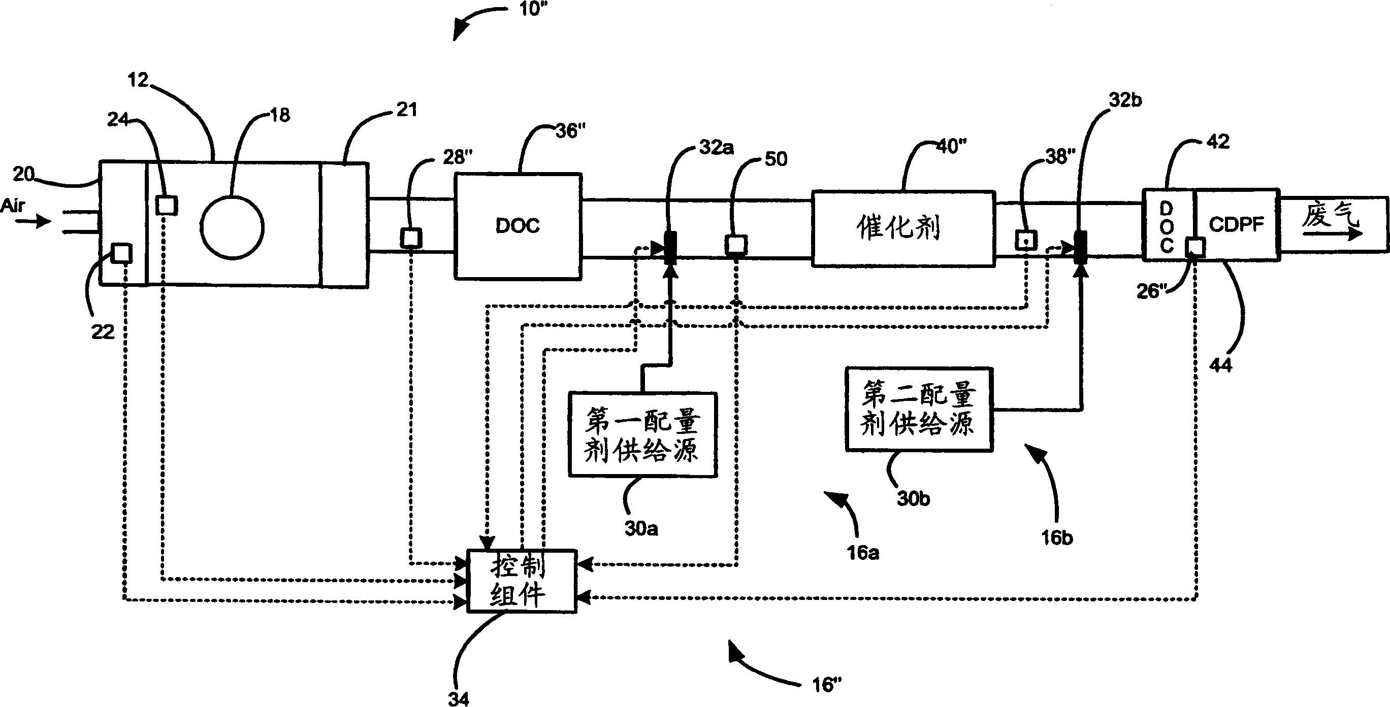
[0021] An engine system 10 is schematically shown in FIG. 1 . The engine system 10 includes an engine 12 , an exhaust system 14 and a dosing system 16 . The engine 12 includes a cylinder 18 , an inlet manifold 20 , a manifold absolute pressure (MAP) sensor 22 and an engine speed sensor 24 . Air flows into the engine 12 through the inlet manifo...


PUM


Abstract

A method of monitoring operation of a dosing system for treating exhaust of an engine includes monitoring a downstream temperature of an exhaust downstream of the dosing system and injecting a dosing agent. A control module determines a temperature differential threshold based on an amount of dosing agent injected and calculates a temperature differential. The control module further evaluates operation of the dosing system based on the temperature differential and the temperature differential threshold.

Description

field of invention [0001] This invention relates to automotive exhaust systems, and more particularly to treating engine exhaust. Background of the invention [0002] Engine work includes the combustion process and the exhaust process. During combustion, an air / fuel mixture is combusted within cylinders to drive pistons (not shown). Vehicle engines produce exhaust gases as a result of the combustion of air and fuel. During exhausting, exhaust gas is released from the cylinders and enters the exhaust system. Exhaust gases contain nitrous oxide (NOx) and carbon monoxide (CO), which are treated before being expelled from the vehicle. [0003] In order to reduce the amount of emissions (eg NOx) in the exhaust gas, an exhaust gas treatment system is used. A control module monitors engine operation and emission values, and a dosing system injects reductant into the exhaust gas upstream of the catalyst. The exhaust gas to be treated reacts with this catalyst and produces a che...

Claims


Application Information

Patent Timeline
Patent Type & Authority Applications(China)
IPC IPC(8): F01N11/00F01N3/18
CPCF01N13/009F01N3/2033F02D41/0235F01N13/02F01N2013/026F01N2550/05F02D41/146F01N2560/026F01N3/0253Y02T10/26Y02T10/47F01N9/00F01N3/035F01N11/002F02D41/1446F01N13/0097Y02T10/12Y02T10/40
Inventor D·B·布朗M·J·小帕拉托尔M·B·维奥拉
Owner GM GLOBAL TECH OPERATIONS LLC
Learn More