Pipe line-closing device

A sealing device and pipeline technology, applied in the directions of water supply devices, pipe components, water supply main pipes, etc., can solve the problem of losing the locking function of the locking link, and achieve simplicity, relaxation, noise reduction, and impact. The effect of softening and noise

Active Publication Date: 2006-12-06
WATERWORKS TECH DEV ORG CO LTD
View PDF1 Cites 1 Cited by
  • Summary
  • Abstract
  • Description
  • Claims
  • Application Information

AI Technical Summary

Problems solved by technology

If such an overturned state of the locking link pair 13, 14 occurs, the

Method used


Image

  • Pipe line-closing device
  • Pipe line-closing device
  • Pipe line-closing device

Examples


no. 1 Embodiment approach

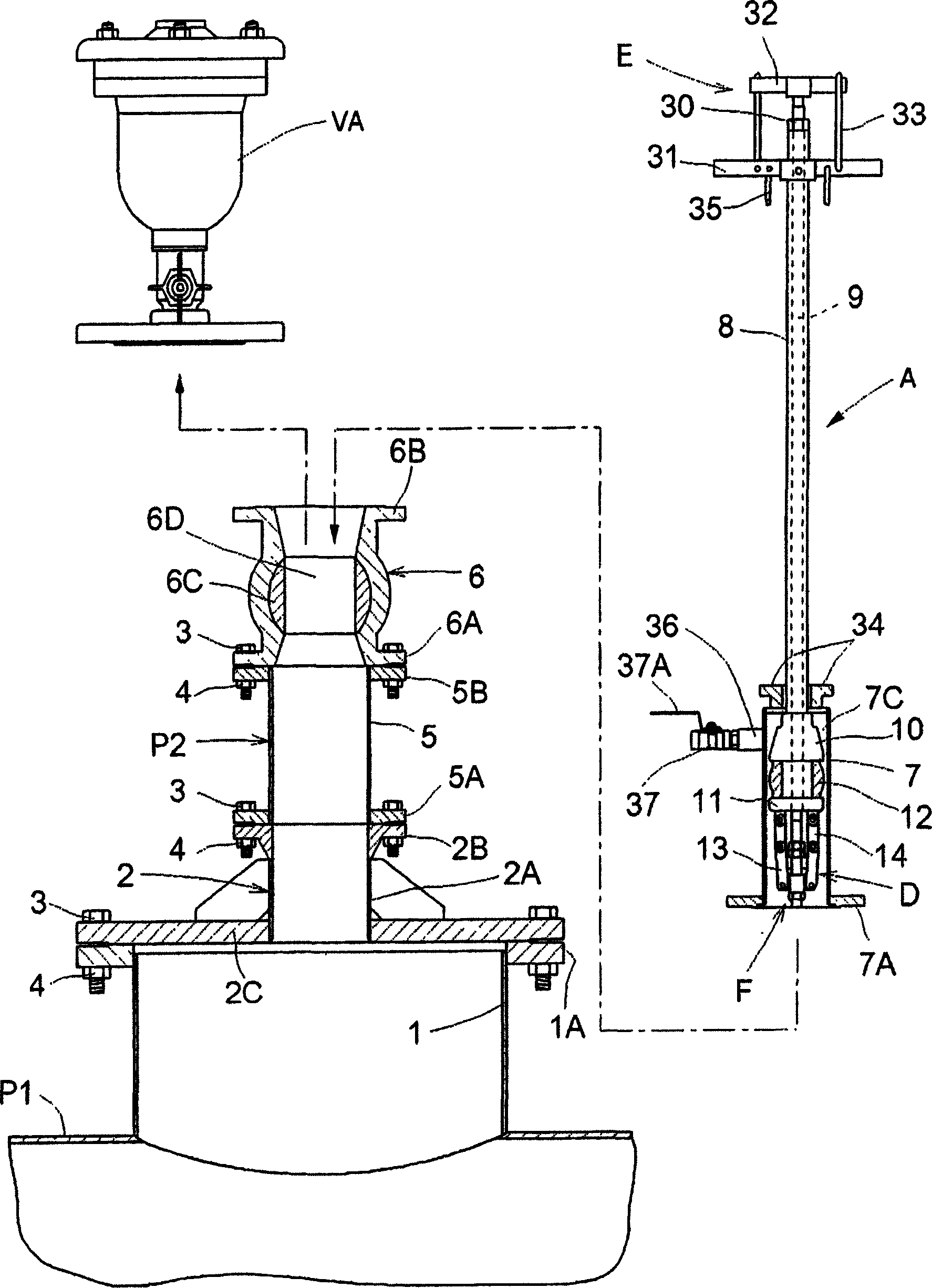
[0059] The following description will be made with reference to the accompanying drawings of the pipeline sealing device A used in the case where the flow of water from the branch pipe can be prevented even if the water supply in the water main pipe P1 is performed, and the valve replacement method using the pipeline sealing device A. In the state of P2 leaking, replace the gate valve 6 clamped in the branch pipe P2 with a new gate valve 6 .

[0060] figure 1 Represents a branch connection configuration midway in a fluid delivery path. In this branch pipe connection structure, a connection cover having a connection pipe portion 2A having a diameter smaller than its inner diameter is detachably fixed and detachably connected to the connection flange portion 1A of the branch pipe portion 1 via bolts 3 and nuts 4 in a sealed state. body 2, the branch pipe portion 1 is integrally protrudingly formed in the middle of a water main pipe P1 as an example of a main pipe for fluid tra...

no. 2 Embodiment approach

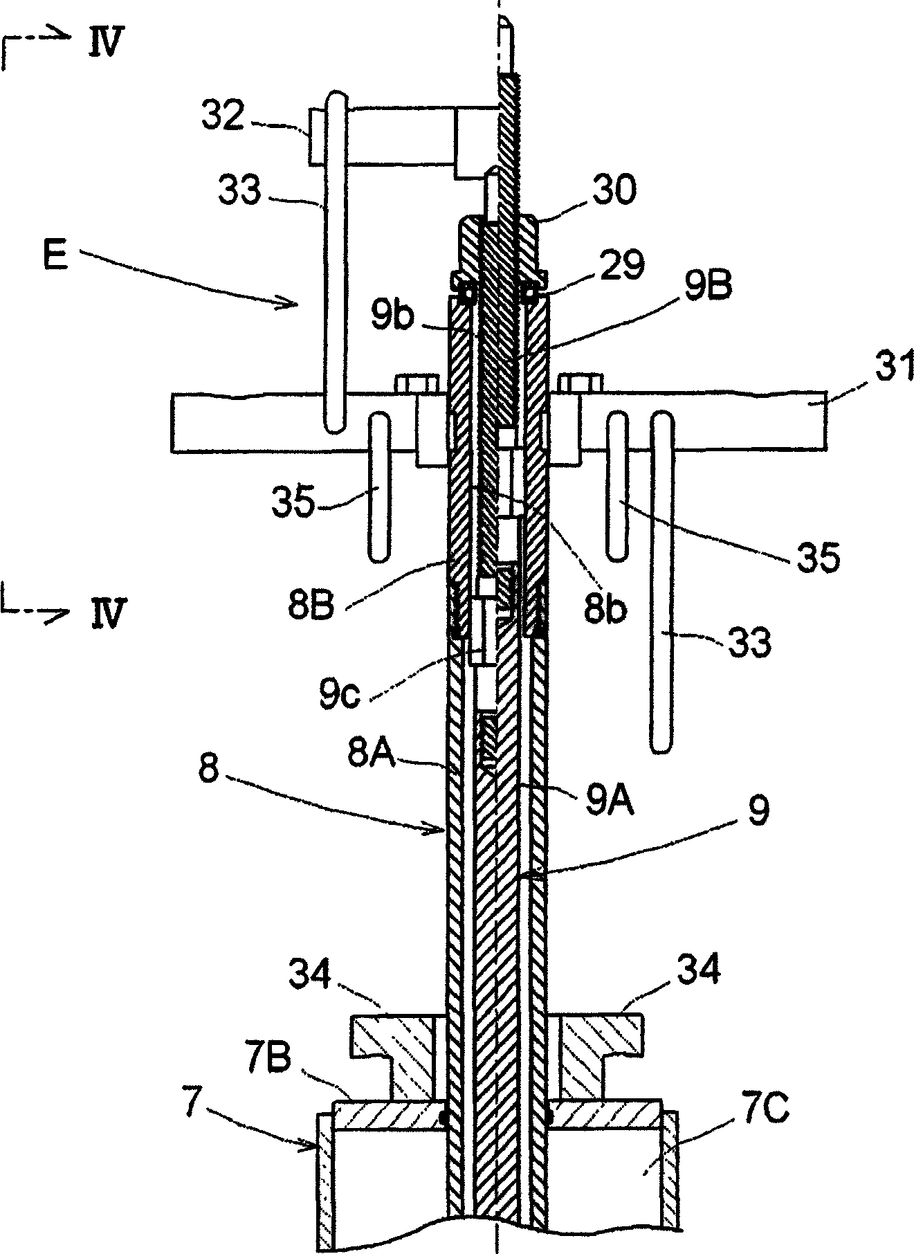
[0092] In the above-mentioned first embodiment, it is configured that the first pressing plate 10 is moved close to the second pressing plate 11 by artificially tightening the screw member 30, but it may also be as follows: Figure 13 As shown, it is configured such that the first pressing plate 10 is moved close to the second pressing plate 11 by a pair of hydraulic jacks 40 .

[0093] That is, on the operation extension cylinder shaft 8B of the first operation shaft 8, a pair of first push operation levers 31 are detachably fitted and held, and a hydraulic pressure lever 31 is attached to each first push operation lever 31 through a bolt 42. The mounting plate 41 of the jack 40. Furthermore, a substantially T-shaped operating arm 43 having a pressure receiving surface 43a that can abut against the end of the piston rod 40A of the hydraulic jack 40 is detachably screwed to the operation extension shaft 9B of the second operating shaft 9 .

[0094] In addition, other structur...

no. 3 Embodiment approach

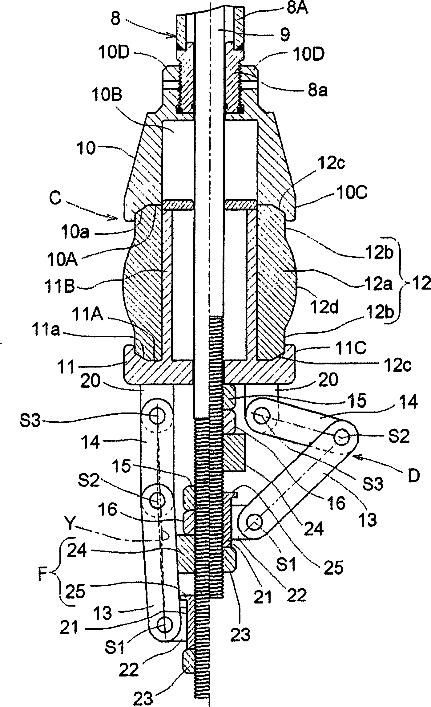
[0096] Figure 14Shows an improvement of the anti-turnover mechanism F, which abuts against the pair of locking links 13 and 14 of the anti-loosening mechanism D to restrict them when the pair of locking links 13 and 14 are extended and operated to reduce their diameters. In the following predetermined outer bending posture, the bent pivot support portion S2 of the locking link pair 13 , 14 protrudes outward in the radial direction. On the downstream side end of the metal mounting cylinder 21, a straightening flange portion 25 is integrally formed. Abutting each upstream locking link 13 is held in the outer bending posture closest to the set limit of the line segment Y. In addition, an elastic correction ring 45 made of elastically deformable urethane rubber or the like is externally installed between the correction flange portion 25 and the second connecting portion 22, and the elastic correction ring 45 moves toward a diameter-shrinking posture as the locking link faces. I...


PUM


Abstract

A pipeline closing apparatus comprises a lid member attachable to a downstream end portion of a sluice valve, a first control shaft 8 extending through the lid member, a second control shaft 9 extending through the first control shaft 8, an elastic annular member 12 disposed between pressing plates 10 and 11 provided on inward end regions of the control shafts 8 and 9 and elastically deformable to a diameter-increased position by being clamped and pressed, thereby to block between an inner peripheral surface of a branch pipe and the pressing plates, and a retaining device D provided between the inward end region of the second control shaft 9 and the upstream pressing plate 11 and including engaging link pairs 13 and 14 flexing and bulging to a diameter-increased position in response to outward sliding movement of the second control shaft 9 relative to the first control shaft 8. The apparatus further comprises a reversal preventing device F which, when the engaging link pairs 13 and 14 of the retaining device are stretched to a diameter-reduced position, contacts and limits the engaging link pairs 13 and 14 to an outwardly bent position where flexing pivotal portions of the engaging link pairs 13 and 14 project radially outward.

Description

technical field [0001] The present invention relates to a pipeline sealing device used, for example, when replacing a gate valve or a butterfly valve sandwiched in a fire hydrant whose branch is connected to the main waterway in a state where water leakage from a branch pipe is prevented even if water is sent in the main waterway. In the branch pipe used or air valve. Background technique [0002] In the previous pipeline sealing device, such as Figure 21 As shown, there is provided: a bottomed cylindrical cover body 7, which can be installed on the downstream end of the gate valve, so that the branch is connected to the main pipe for fluid delivery, and the end opening of the branch pipe with the gate valve is sandwiched between them. closed; the cylindrical first operating shaft 8, in a sealed state, freely slides through the cover body 7 along the axial direction; the second operating shaft 9, freely slides through the first operating shaft 8 along the axial direction; ...

Claims


Application Information

Patent Timeline
IPC IPC(8): F16L55/00E03B7/00E03B7/07F16L55/10F16L55/12
Inventor 酒井笃史
Owner WATERWORKS TECH DEV ORG CO LTD
Why Eureka
Try Eureka