Lightning arrestor
A technology for lightning arresters and insulating components, which is applied in the field of lightning arresters, can solve the problems of high mechanical strength against bending, high manufacturing costs, and difficulties, and achieve the effects of reducing manufacturing costs and excellent pressure release performance
- Summary
- Abstract
- Description
- Claims
- Application Information
AI Technical Summary
Problems solved by technology
Method used
Image
Examples
Embodiment approach 1
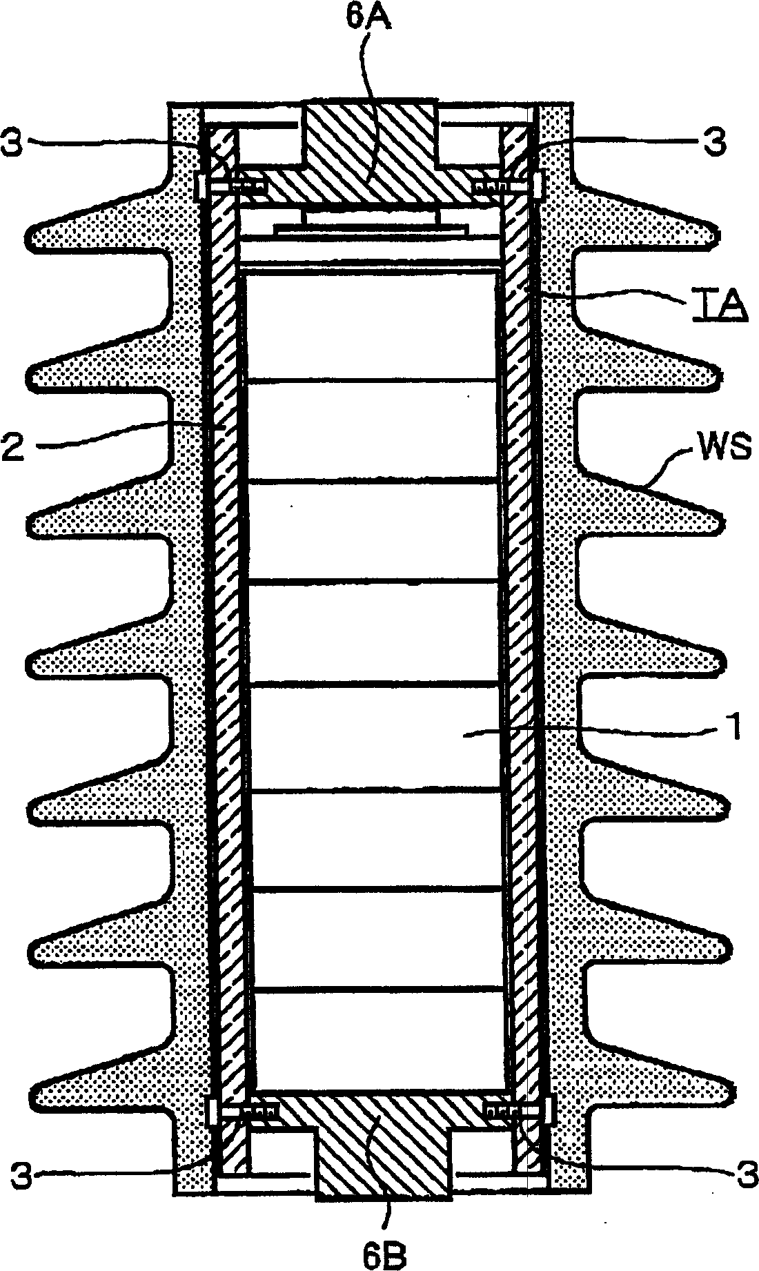
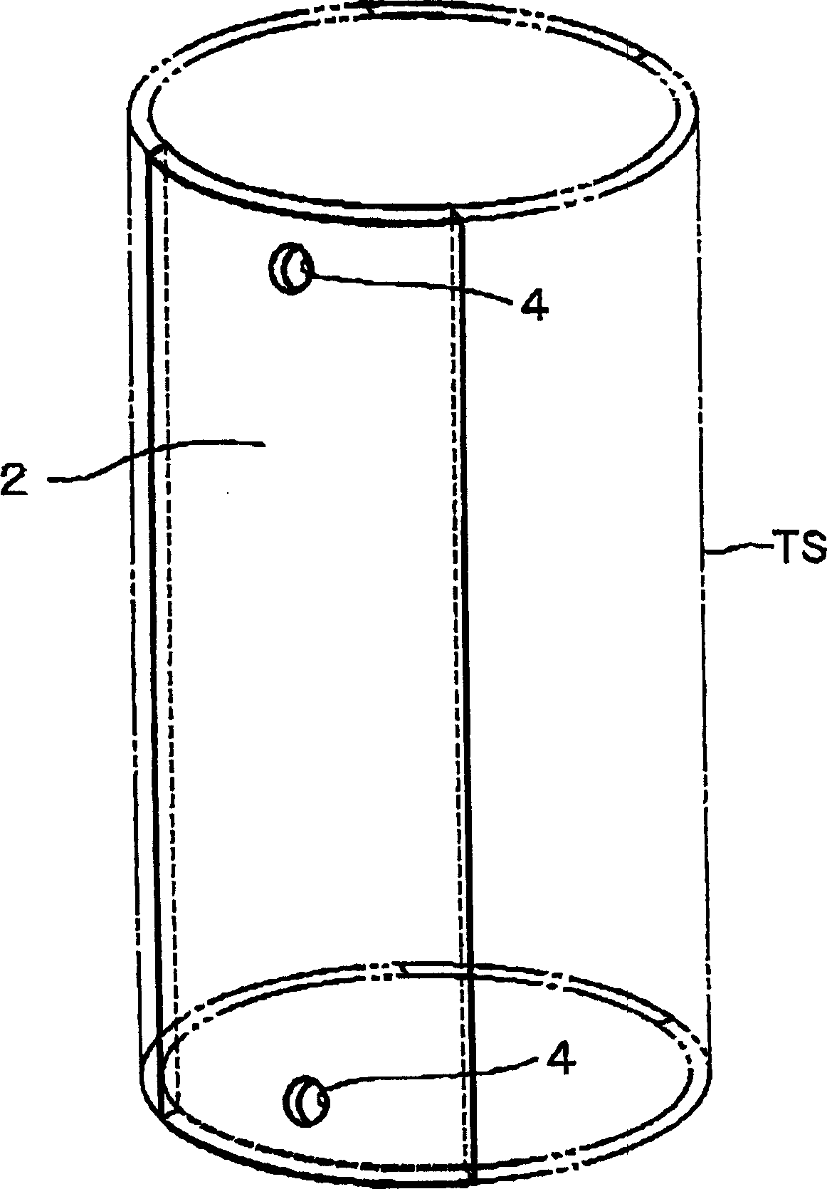
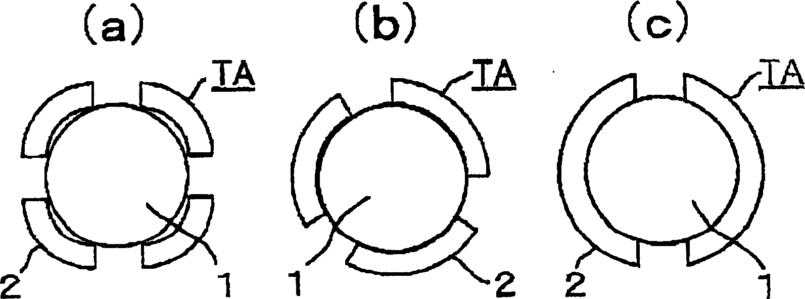
[0025] Below, refer to Figure 1 to Figure 6 Embodiment 1 of the present invention will be described. figure 1 It is a longitudinal sectional view showing the overall configuration of the lightning arrester according to Embodiment 1 of the present invention. figure 2 It is a schematic diagram showing a structure in which a part of an insulating cylinder is cut away to form a gutter-shaped insulating body, which shows the structure of Embodiment 1 of the present invention. image 3 It is a cross-sectional view showing the case where the gutter-shaped insulator according to Embodiment 1 of the present invention is arranged around the zinc oxide element. Figure 4 It is a cross-sectional view showing the configuration of Embodiment 1 of the present invention, and is a cross-sectional view showing means for fixing a gutter-shaped insulator to an electrode part. Figure 5 It is a cross-sectional view visually showing a state in which pressure-increased gas is released from the ...
Embodiment approach 2
[0038] use Figure 7 Embodiment 2 of the present invention will be described, Figure 7 It is a schematic diagram showing the configuration of a gutter-shaped insulator produced by cutting a part of the insulating cylinder according to Embodiment 2 of the present invention.
[0039] In this second embodiment, configurations other than the unique configurations described here have the same configurations as those of the first embodiment described above, and have the same functions. The same reference numerals in the figures indicate the same or corresponding parts.
[0040] Showing the structure of the gutter-shaped insulator of Embodiment 2 of the present invention Figure 7 , is in figure 2 A configuration developed on the basis of Embodiment 1 shown in . In addition to the structure of Embodiment 1, in order to release the pressure-increased internal gas smoothly and quickly, the downpipe-shaped insulator 2 is provided with a pressure release hole in addition to the fix...
Embodiment approach 3
[0043] use Figure 8 Embodiment 3 of the present invention will be described, Figure 8 It is a schematic diagram showing the configuration of a gutter-shaped insulator produced by cutting a part of the insulating cylinder according to Embodiment 3 of the present invention.
[0044] In this third embodiment, the configurations other than the unique configurations described here have the same configurations as those of the second embodiment described above, and have the same functions. The same reference numerals in the figures indicate the same or corresponding parts.
[0045] Showing the structure of the gutter-shaped insulator of Embodiment 3 of the present invention Figure 8 , to represent Figure 7 A modified example of Embodiment 2 shown in .
[0046] When the number of cutouts from the insulating tube TS is reduced and as a result, the number of downpipe-shaped insulators 2 is also small, since the width of the downspout-shaped insulators 2 becomes wider (since the ...
PUM
 Abstract
Description
Claims
Application Information
 - R&D
- Intellectual Property
- Life Sciences
- Materials
- Tech Scout
- Unparalleled Data Quality
- Higher Quality Content
- 60% Fewer Hallucinations
Browse by: Latest US Patents, China's latest patents, Technical Efficacy Thesaurus, Application Domain, Technology Topic, Popular Technical Reports.
© 2025 PatSnap. All rights reserved.Legal|Privacy policy|Modern Slavery Act Transparency Statement|Sitemap|About US| Contact US: help@patsnap.com


