
Vehicle power transmission device

A technology for power transmission devices and vehicles, which is applied to power devices, air pressure power devices, transmission devices, etc., can solve problems such as uneven load distribution, and achieve the effect of uniform load distribution

Active Publication Date: 2015-04-29
HONDA MOTOR CO LTD
View PDF4 Cites 0 Cited by
  • Summary
  • Abstract
  • Description
  • Claims
  • Application Information

AI Technical Summary

Problems solved by technology

Therefore, the load distribution received by the rolling elements of the ball bearing supporting the large end portion 903 becomes uneven.

Method used


Image

  • Vehicle power transmission device
  • Vehicle power transmission device
  • Vehicle power transmission device

Examples


Embodiment Construction

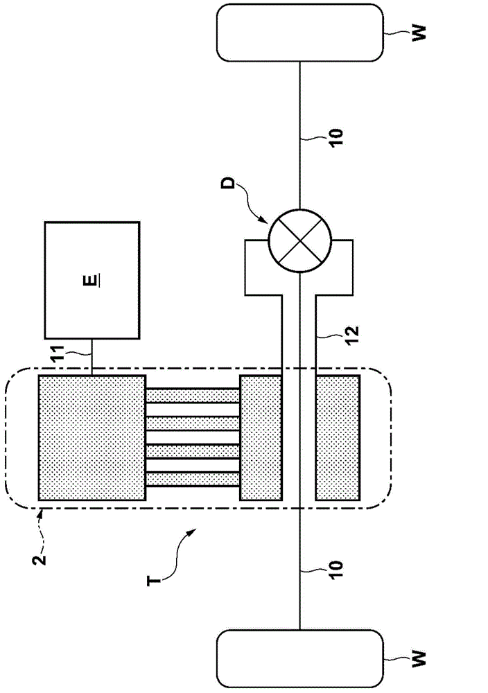
[0028] Below, based on Figure 1 to Figure 8 A-8C describes embodiments of the present invention. like figure 1 As shown, a power transmission device for a vehicle that transmits driving force of an engine E as a driving source to driving wheels W, W via left and right axle shafts 10 , 10 includes a crank-type continuously variable transmission T and a differential D.

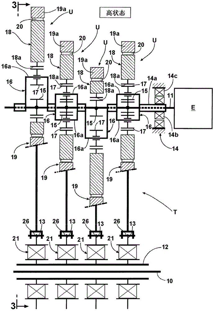
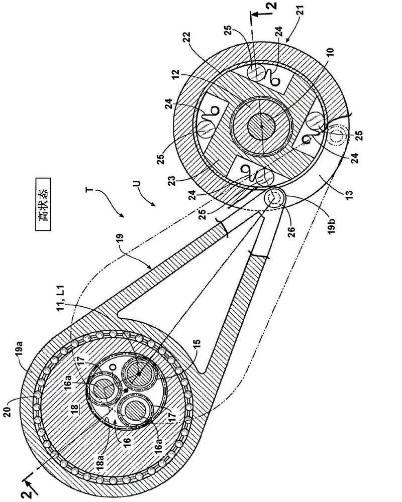
[0029] Next, based on Figure 2 to Figure 6 A-6D The structure of the continuously variable transmission T is explained. like figure 2 and image 3 As shown, the continuously variable transmission T of this embodiment is formed by stacking a plurality of (four are shown in the embodiment) power transmission units U having the same structure in the axial direction, and these power transmission units U have A common input shaft 11 and a common output shaft 12 are arranged in parallel, and the rotation of the input shaft 11 is decelerated or accelerated and transmitted to the output shaft 12 .

[0030] Her...


PUM


Abstract

The invention provides a vehicle power transmission device. A connecting rod is provided with an annular big end part, a small end part and a connection part. The big end part is pressed in to a bearing arranged on the peripheral face of an eccentric disc. The small end part is connected with a swinging part. The connection part connects the big end part and the small end part and is provided with a shrink neck part and a rib part. The shrink part is arranged to fail to interface with a one-way clutch when the swinging rod swings. The rib part is arranged on the side face on the other side opposite to the side face, formed towards the one-way clutch, of one side of the shrink neck part.

Description

technical field [0001] The present invention relates to a power transmission device for a vehicle. Background technique [0002] In German Patent Application Publication No. DE 10 2009 031 791 A1, a vehicle power transmission device with such a structure is disclosed: the large end of the connecting rod is connected to an eccentric disc, and the eccentric disc is connected to the input of the engine. The shaft rotates integrally, and connects the small end of the connecting rod to the output shaft via the one-way clutch. In this vehicle power transmission device, the reciprocating motion of the link generated by the eccentric rotation of the eccentric disc is converted into the unidirectional rotational motion of the output shaft by the one-way clutch. [0003] Figure 9 A. Figure 9 B is a diagram showing an outline of a link of a conventional vehicle power transmission device. The link 900 has a large end portion 903 and a small end portion 905 . In order to prevent int...

Claims


Application Information

Patent Timeline
Patent Type & Authority Applications(China)
IPC IPC(8): B60K6/543
CPCF16H29/04
Inventor 西村优史
Owner HONDA MOTOR CO LTD
Learn More