Method of automatically setting reconstructed view field along inner chest cavity border in CT locating image

An inner boundary and positioning image technology, which is applied in patient positioning for diagnosis, image enhancement, image analysis, etc., can solve the problems of inaccurate boundaries, time-consuming, and increasing the patient's physical and psychological burden, so as to prevent linear The effect of artifacts

Active Publication Date: 2007-01-03
SIEMENS SHANGHAI MEDICAL EQUIP LTD
View PDF0 Cites 15 Cited by
  • Summary
  • Abstract
  • Description
  • Claims
  • Application Information

AI Technical Summary

Problems solved by technology

[0006] The above-mentioned setting of manually adjusting the FOV has great disadvantages. First, in order to obtain the best display range and effect, the boundary of the FOV should be tangent to the outermost point on the boundary of the patient's thoracic cavity. Manually adjust the boundary of the FOV It is

Method used


Image

  • Method of automatically setting reconstructed view field along inner chest cavity border in CT locating image
  • Method of automatically setting reconstructed view field along inner chest cavity border in CT locating image

Examples


Embodiment Construction

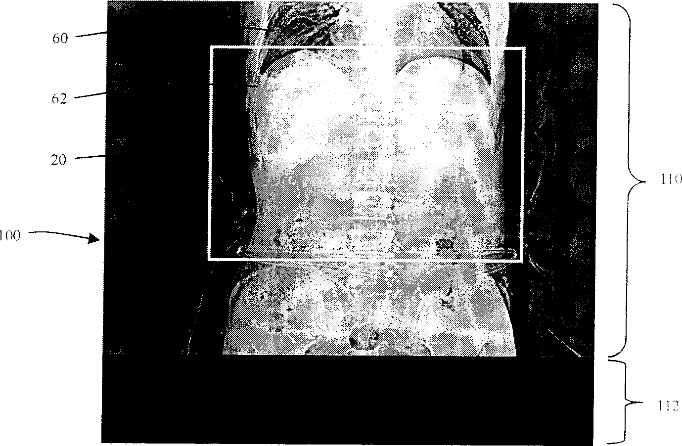
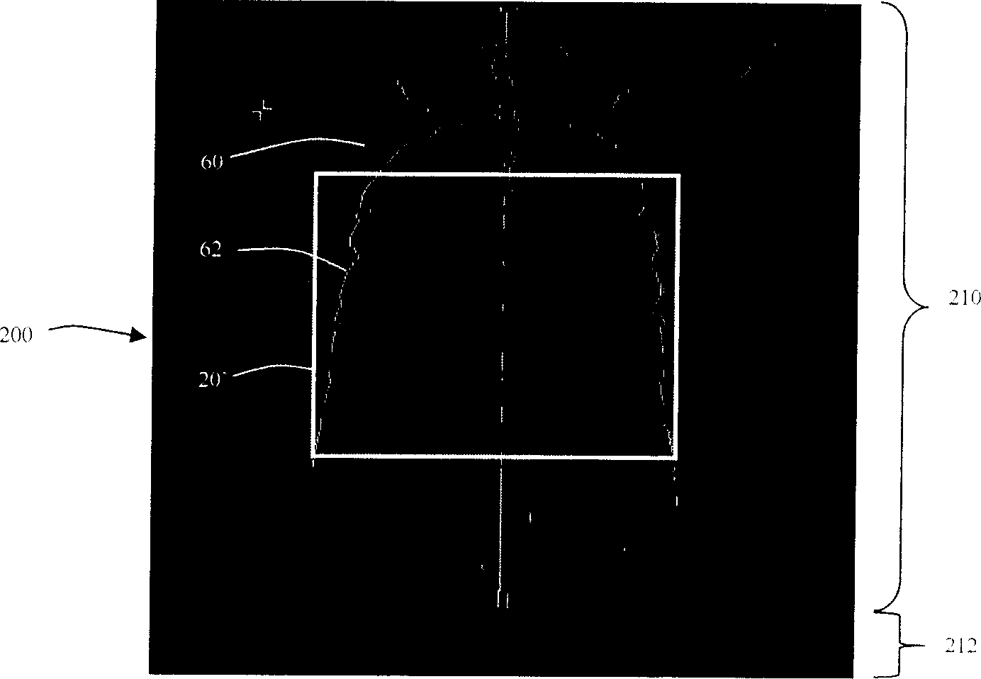
[0020] The scout images of the CT equipment are represented by different gray scales, which reflect the degree of absorption of X-rays by human organs and tissues. In the scout image, black shadows indicate low-absorption areas, that is, low-density areas, such as lungs; white shadows indicate high-absorption areas, that is, high-density areas, such as bones. In actual work, CT values ​​are often used to indicate the level of density. Generally, the CT values ​​of air, fat, water, soft tissue, and bone on the positioning image increase sequentially. The method of the present invention utilizes some known knowledge about human body positioning images, such as: the inner boundary of the thoracic cavity is surrounded by bones, and the CT values ​​of the bones are larger than those of other positions and sick beds.

[0021] In the present invention, after the scan range is set on the positioning image, the CT values ​​of various parts of the patient's body are used to search for t...


PUM


Abstract

The present invention relates to method of automatically setting reconstructed view field along inner chest cavity border in CT locating image, and the reconstructed view field contains exactly all the points in inner chest cavity border of the scanned locating image. The present invention obtains the inner chest cavity border in the image of the patient through searching from the skeleton to the chest cavity and comparing the CT values. The method can set reconstructed view field accurately, effectively and quickly.

Description

technical field [0001] The present invention relates to a method for setting a reconstructed field of view (Field of View, hereinafter referred to as FOV) on a positioning image (Topogram, also called Topo image) of computed tomography (Computed Tomography, hereinafter referred to as CT), in particular to a method for A method for automatically setting FOV along the inner thoracic boundary (Contours) on CT positioning images. Background technique [0002] Generally, before the CT equipment starts a series of scans or helical scans, it is necessary to scan a positioning image of the patient, so as to determine the scanning range and perform image reconstruction (Image Reconstruction) positioning through the positioning image. Then, the X-ray source is used to scan the inspected part of the patient to obtain projection data for image reconstruction to generate a medical image. [0003] When scanning the positioning image, the position of the tube as the X-ray source in the CT...

Claims


Application Information

Patent Timeline
IPC IPC(8): A61B6/02A61B6/03A61B6/04
CPCA61B6/469G01N2223/419A61B6/032G06T7/0018G01N23/046G06T7/0083G01N2223/612G06T2207/10116A61B6/545A61B6/488G06T2207/30061G06T2207/10081G06T7/12G06T7/80
Inventor 徐晓东陈马浩赵峰
Owner SIEMENS SHANGHAI MEDICAL EQUIP LTD
Why Eureka
Try Eureka