Eureka AIR delivers breakthrough ideas for toughest innovation challenges, trusted by R&D personnel around the world.

Method for locating and controlling multilane free flow video vehicle

A control method and vehicle positioning technology, which are applied in the field of intelligent transportation, can solve the problems of false detection and missed detection, and can not meet the requirements of vehicle positioning accuracy, and achieve the effects of accurate positioning, improving positioning accuracy and avoiding sticking.

Inactive Publication Date: 2009-01-21
RES INST OF HIGHWAY MIN OF COMM
View PDF0 Cites 78 Cited by
  • Summary
  • Abstract
  • Description
  • Claims
  • Application Information

AI Technical Summary

Problems solved by technology

[0005] In the multi-lane free flow non-stop electronic billing mode, when vehicles pass through the toll area, there may be lane changes and multiple vehicles running in parallel. If the high-speed vehicles are not accurately positioned, false detections and missed detections may occur
[0006] At present, the video detector of the expressway generally adopts the method of setting a virtual coil to cover a lane to detect the condition of the lane. Once a vehicle passes by, the vehicle triggers the virtual coil, and the video detector obtains the specific lane vehicles and lane traffic through data processing. For location information, it can only be determined in a certain lane, and the width range of a single lane of expressway is 3.75 meters, which does not meet the requirements of vehicle positioning accuracy in the free-flow toll mode

Method used


Image

  • Method for locating and controlling multilane free flow video vehicle
  • Method for locating and controlling multilane free flow video vehicle
  • Method for locating and controlling multilane free flow video vehicle

Examples


Embodiment Construction

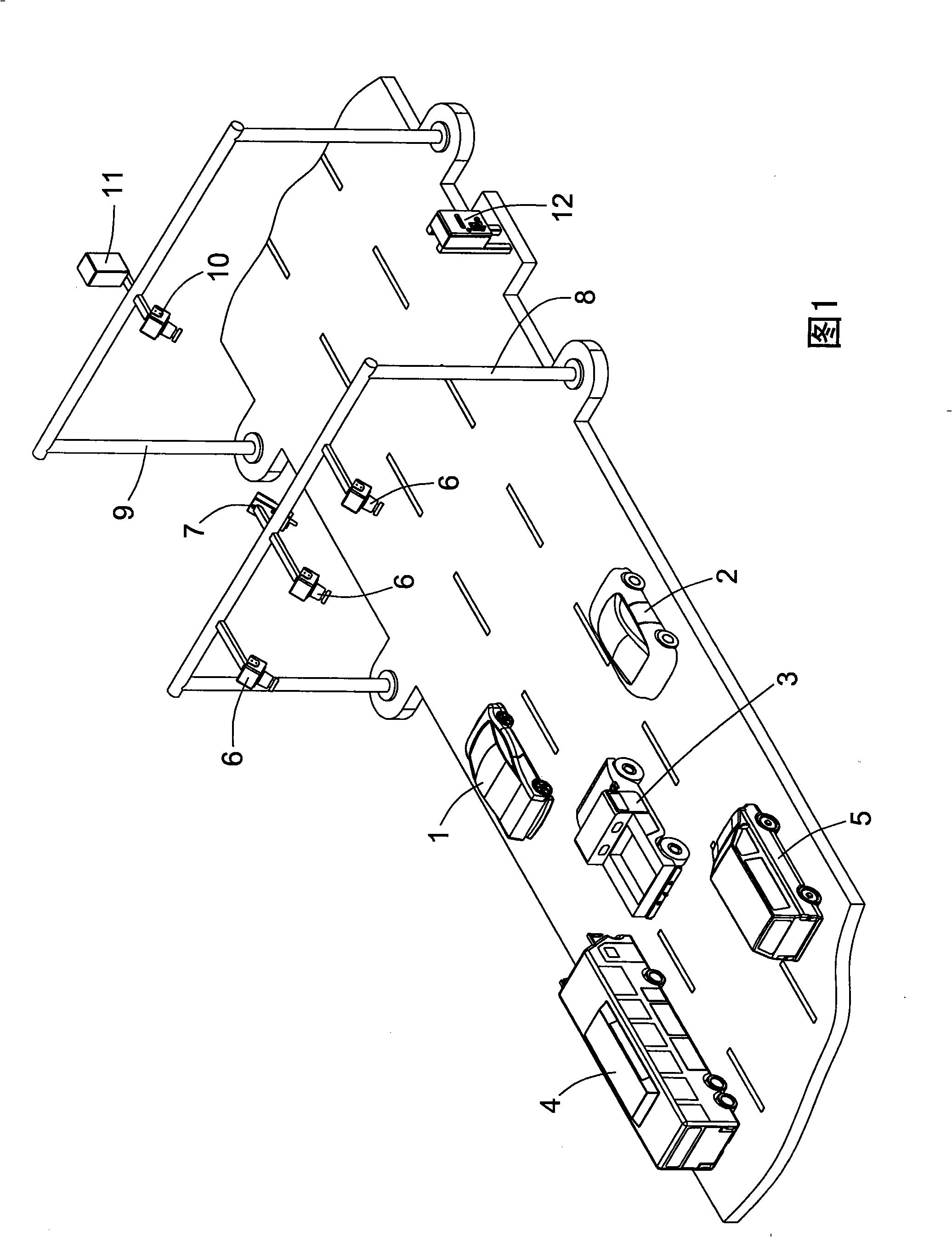
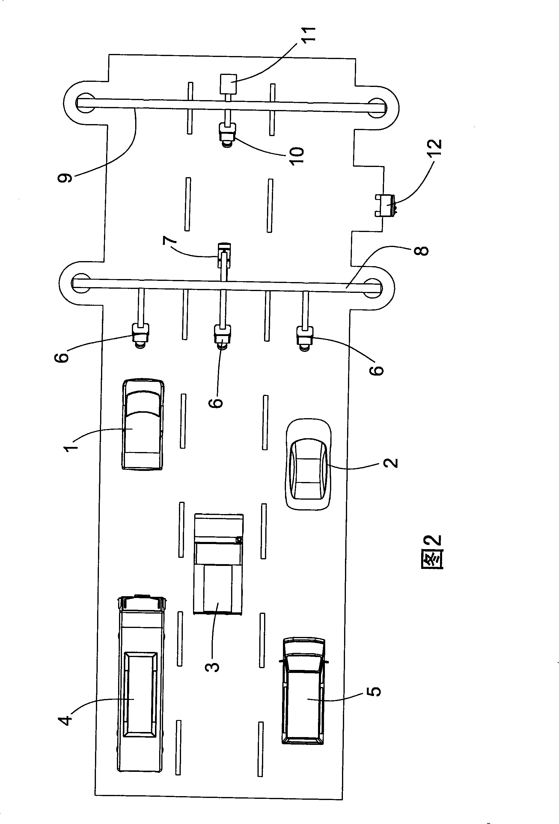
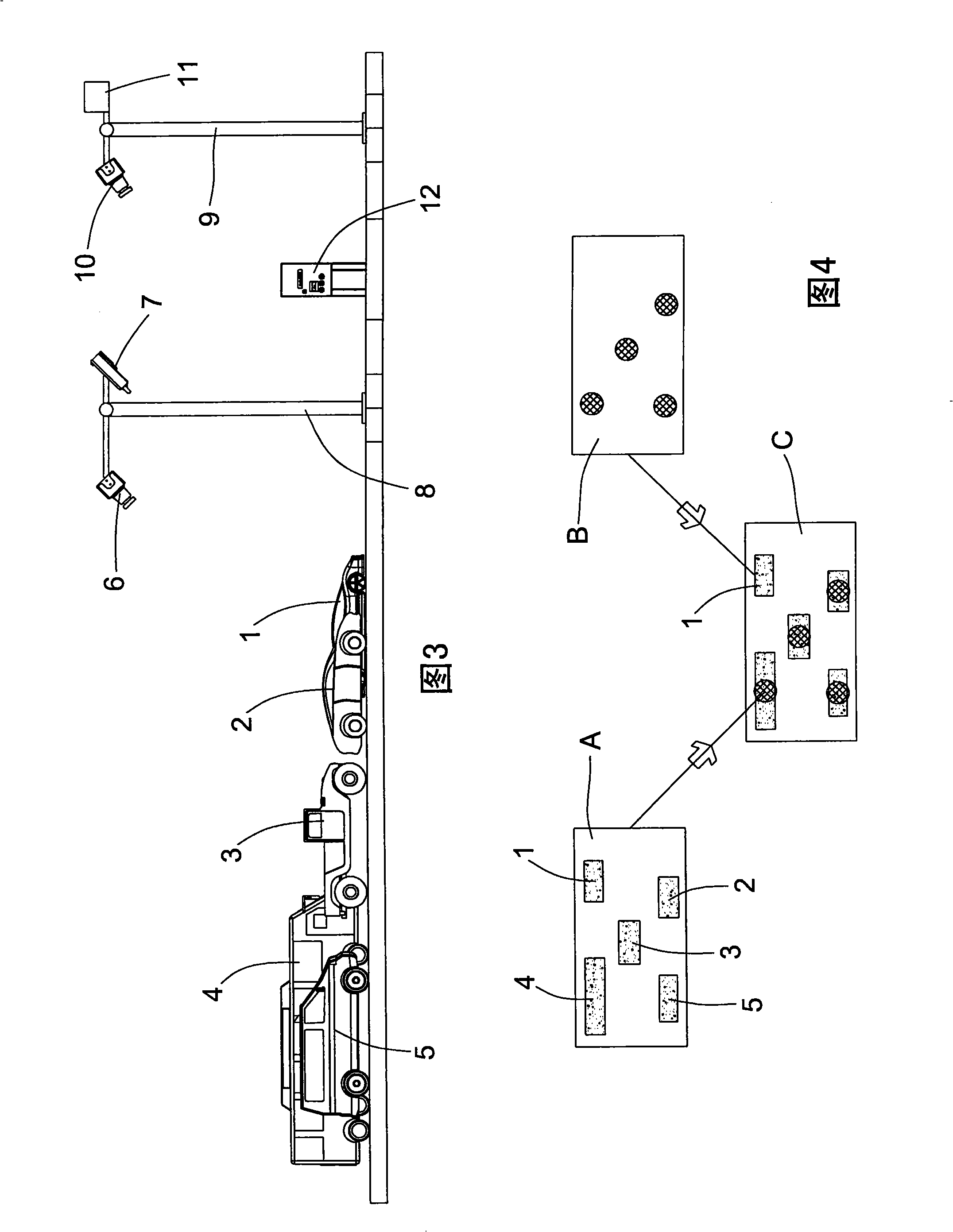
[0036] Please refer to FIG. 1, FIG. 2, and FIG. 3. When implementing this method, some hardware equipment should be installed at the toll station. The hardware equipment mainly includes a snapshot camera 6, a microwave communication antenna 7, a gantry 8, a gantry 9, a panoramic camera 10, License plate recognition system 11 , lane coordination control system 12 .

[0037] The gantry 8 and the gantry 9 are bridged on the road, the gantry 8 is located in front of the gantry 9, and the snapshot camera 6 and the microwave communication antenna 7 are installed on the gantry 8. In this embodiment, there are three lanes on the road, The positions of the three snapshot cameras 6 correspond to the three lanes respectively, the panoramic camera 10 and the video detector 11 are installed on the gantry 9, and the lane coordination control system 12 is installed on one side of the highway.

[0038] Please refer to Image 6 , the lane coordination control system 12 includes a central proc...


PUM


Abstract

The invention relates to a multi-lane free flow video vehicle position and control method, the processes thereof are that: step 1, virtual coils are arranged in the visual field of a panoramic camera to form a detection area. Step 2, when a vehicle enters the detection area, a video detector starts an algorithm program to obtain the position of the vehicle. Step 3, a central processing unit starts a microwave communication system and an image snapshot system. Step 4, a logical comparison system judges whether the vehicle has electronic label information, if without, executing step 8. Step 5, the logical comparison system judges whether a vehicle license plate number in the electronic label information and the vehicle license plate number which is identified by a license plate recognition system are consistent, if not consistent, executing step 8 is. Step 6, the images of the vehicle which are snapshot are deleted. Step 7, toll transaction is done, and a transaction record is formed after the transaction. Step 8, the transaction record which is transferred to a background billing system is further treated. Step 9, returning to a main process. The method can achieve an electronic toll collection function in a multi-lane free flow mode through the accurate location for the vehicle and the coordination control for a system.

Description

technical field [0001] The invention belongs to the technical field of intelligent transportation, and relates to a video vehicle positioning and coordinated control method of a free-flow electronic toll collection system, which can complete electronic toll collection in a free-running state of the vehicle. Background technique [0002] With the continuous expansion of the city scale, the rapid development of expressways, the rapid growth of urban traffic flow, and the substantial increase in traffic density, new requirements have been put forward for the vehicle capacity of road toll stations. [0003] The traditional manual and semi-automatic charging method must be "parking-paying-starting", and vehicle congestion often occurs. At present, the ETC electronic non-stop toll collection system adopted in China still needs to have toll booths and automatic railings. When vehicles pass through toll booths, they must drive along a certain lane, and the traffic capacity of vehicl...

Claims


Application Information

Patent Timeline
IPC IPC(8): G07B15/00G08G1/04G07B15/06
Inventor 王东柱刘鸿伟肖迪刘杰马晓姣张北海
Owner RES INST OF HIGHWAY MIN OF COMM
Why Eureka
Eureka Blog
Learn More