Link rod of closed compressor and its production

A production method and compressor technology, applied in the direction of connecting rods, mechanical equipment, machines/engines, etc.

Inactive Publication Date: 2007-01-17
LG ELECTRONICS (TIANJIN) APPLIANCES CO LTD
View PDF0 Cites 2 Cited by
  • Summary
  • Abstract
  • Description
  • Claims
  • Application Information

AI Technical Summary

Problems solved by technology

[0019] The purpose of the present invention is to provide a new connecting rod of a hermetic compressor and its manufacturing method. The technical problem to be solved is to minimize the deformation of the inner diameter of the crankshaft connecting part, so that it is more suitable for practical use.

Method used


Image

  • Link rod of closed compressor and its production
  • Link rod of closed compressor and its production
  • Link rod of closed compressor and its production

Examples


Embodiment Construction

[0050] In order to further explain the technical means and effects of the present invention to achieve the intended purpose of the invention, the specific implementation of the connecting rod of the hermetic compressor proposed according to the present invention and its manufacturing method will be described below in conjunction with the accompanying drawings and preferred embodiments. , structure, method, step, feature and effect thereof, detailed description is as follows. If the constituent elements of the prior art are the same, the same symbols are used for description.

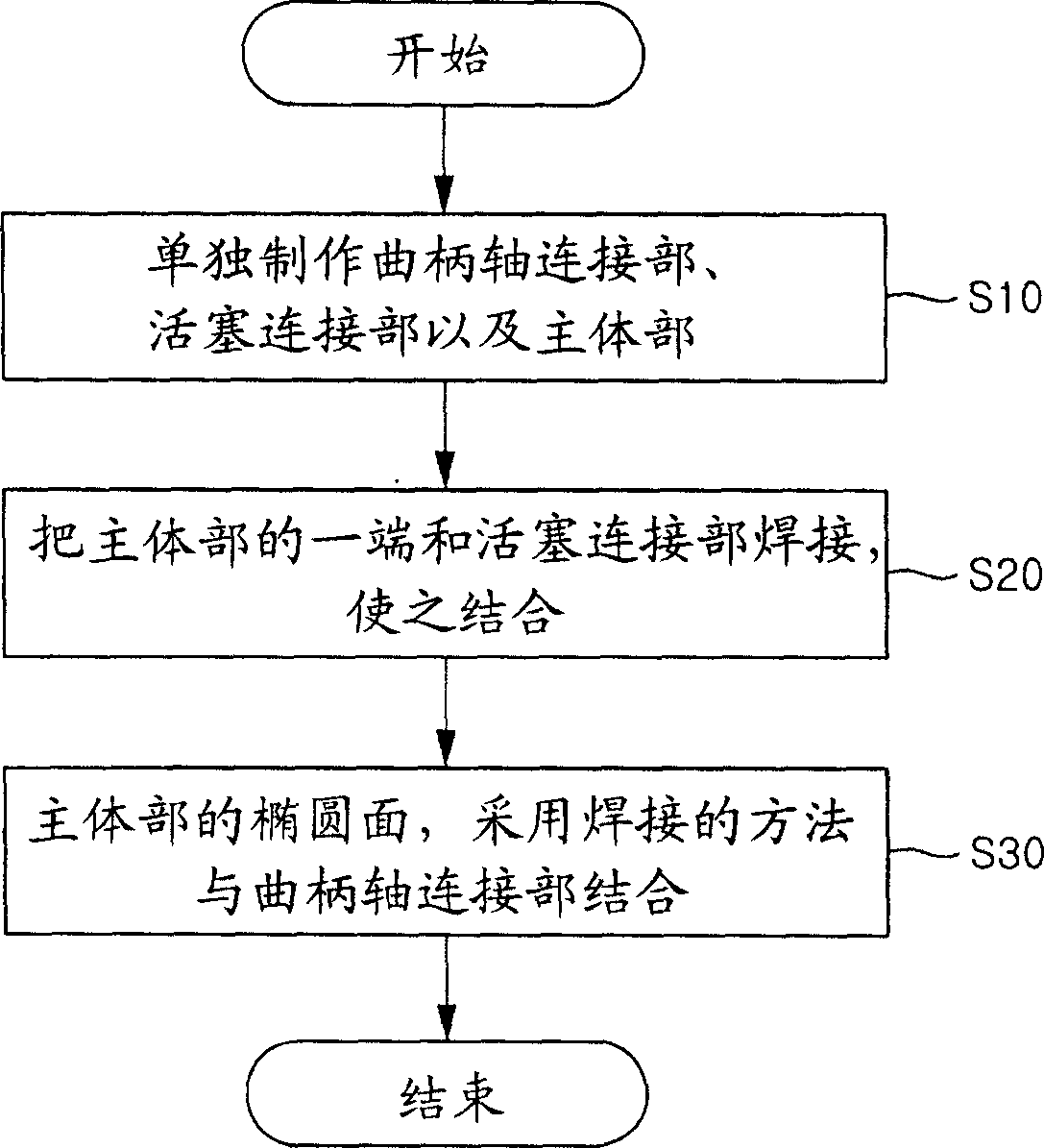
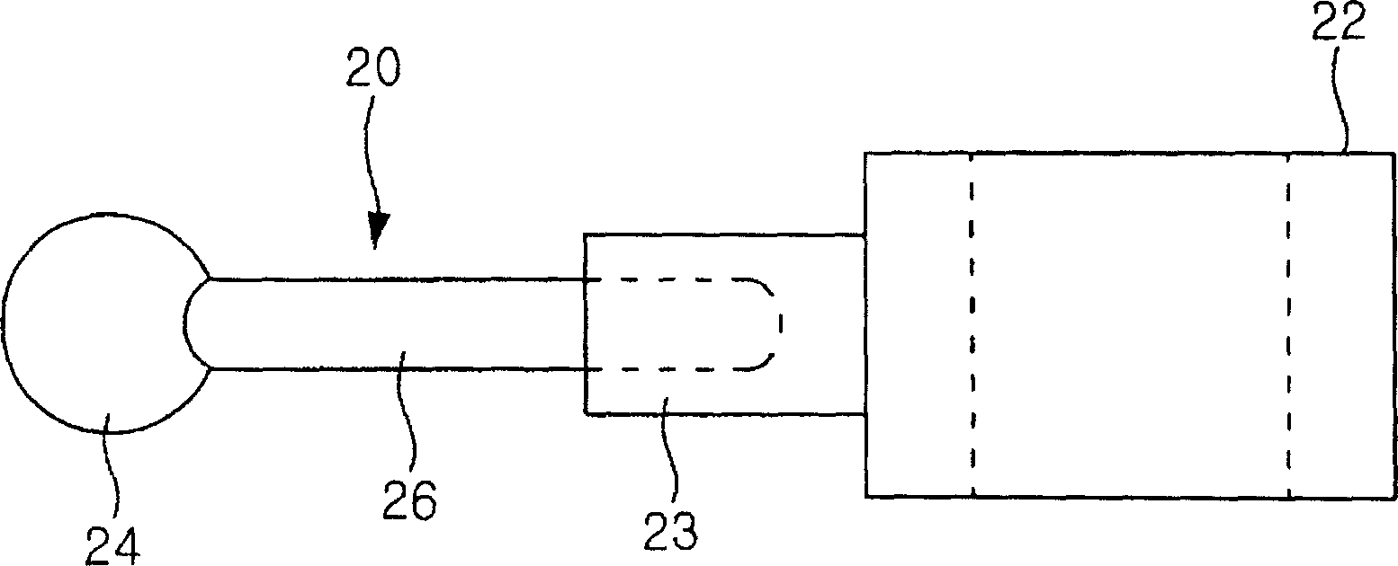
[0051] image 3 It is a side view of the structural composition of the preferred embodiment of the connecting rod according to the present invention, Figure 4 It is a schematic flow chart of steps according to a preferred embodiment of the manufacturing method of the connecting rod of the present invention, Figure 5a and 5b is a schematic diagram of the composition of the manufacturing steps accordi...


PUM


Abstract

This is a kind of connecting rod of hermetic compressor and its producing method. The connecting rod includes piston connecting part set in the piston and connected to the inside of piston in certain angular range; main body part with its one end connected to the said piston connecting part; and crank axle-connecting part that envelops the other end of the said main body part and is set at the other end of the said main body part. The producing method includes piston connecting part and main body part are produced; one side of the said piston connecting part and one end of the said main body part are combined; the other end of main body part is enveloped in the crank axle connecting part in order to make the crank axle connecting part assemble at the other end of the said main body part.

Description

technical field [0001] The present invention relates to a hermetic compressor, in particular to a connecting rod of a hermetic compressor composed of a crankshaft connecting part, a piston connecting part and a main body and a manufacturing method thereof. Background technique [0002] figure 1 It is a sectional view of the internal structure of a hermetic compressor manufactured by the prior art. As shown in the figure, the airtight container includes an upper container 1 t and a lower container 1 b. A frame 2 is arranged inside the airtight container 1 , and a stator 3 is arranged in the frame 2 . The above-mentioned frame 2 is arranged inside the airtight container 1 and supported by the spring 2s. [0003] Then, a crankshaft 5 is provided through the center of the frame 2 . The crankshaft 5 rotates together with the rotor 4 due to the mutual electromagnetic interaction between the rotor 4 and the stator 3 integrally formed therewith. The upper end of the crankshaft 5...

Claims


Application Information

Patent Timeline
Patent Type & Authority Applications(China)
IPC IPC(8): F04B39/00F04B53/14F16C7/00
Inventor 孙容旭
Owner LG ELECTRONICS (TIANJIN) APPLIANCES CO LTD
Why Eureka
Try Eureka