
Circuit interrupter that produces snap-action connection and disconnection between electrical contacts

A technology of contacts and actuators, used in circuits, electrical switches, contact engagement, etc.

Active Publication Date: 2007-01-17
DEFOND COMPONENTS +1
View PDF3 Cites 7 Cited by
  • Summary
  • Abstract
  • Description
  • Claims
  • Application Information

AI Technical Summary

Problems solved by technology

This situation poses a potential risk to nearby materials, equipment and people, including operators

Method used


Image

  • Circuit interrupter that produces snap-action connection and disconnection between electrical contacts
  • Circuit interrupter that produces snap-action connection and disconnection between electrical contacts
  • Circuit interrupter that produces snap-action connection and disconnection between electrical contacts

Examples


Embodiment Construction

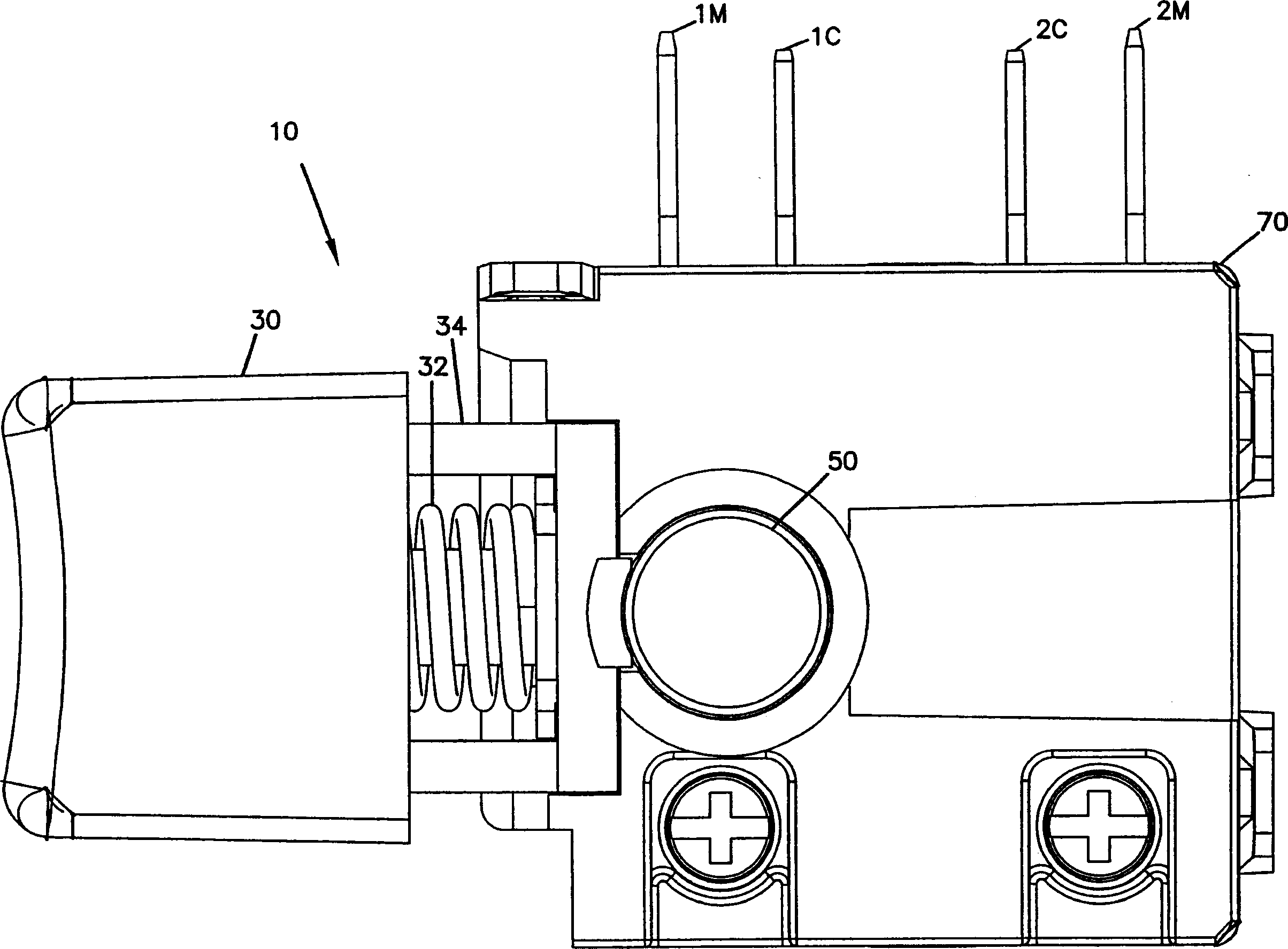
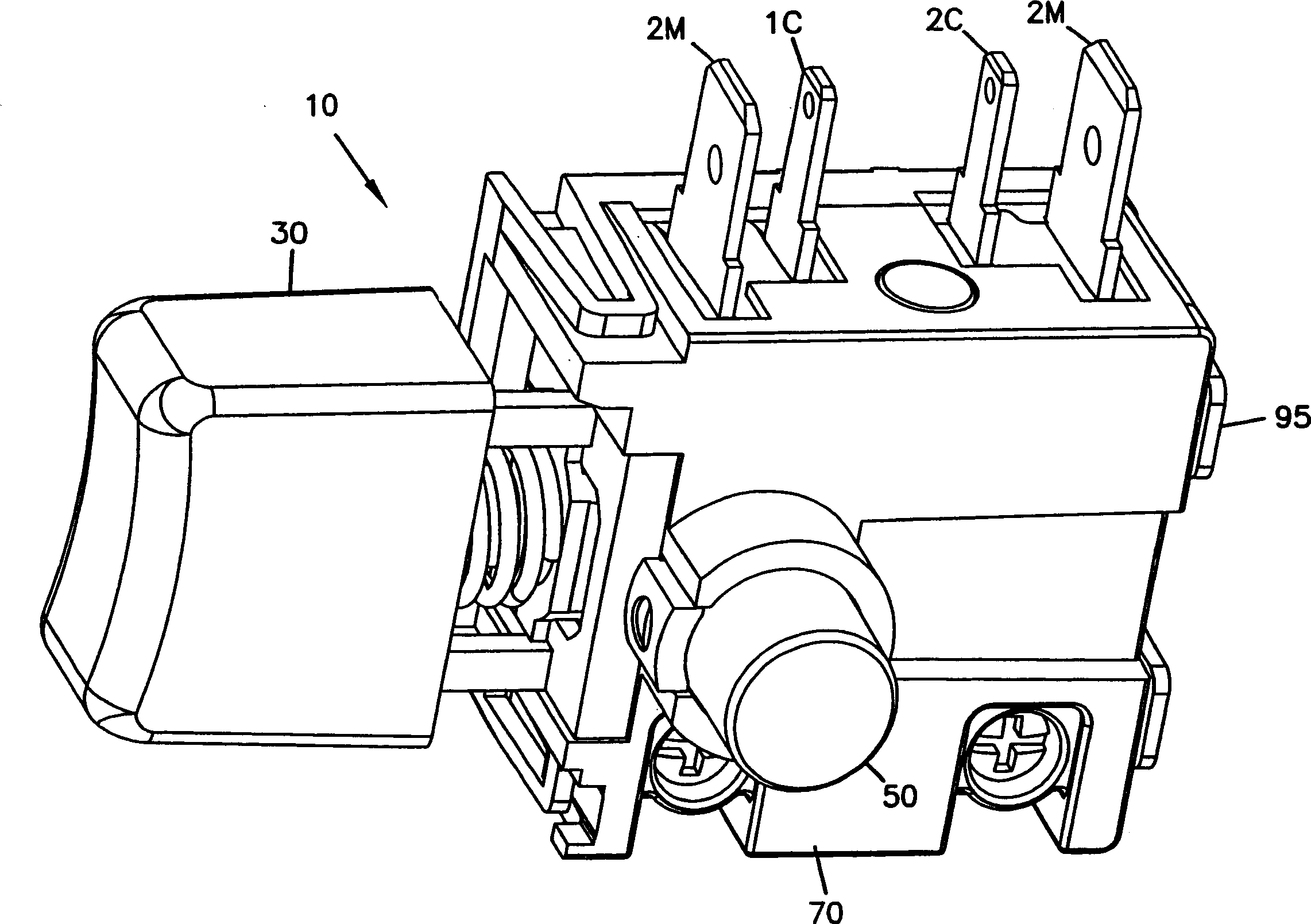
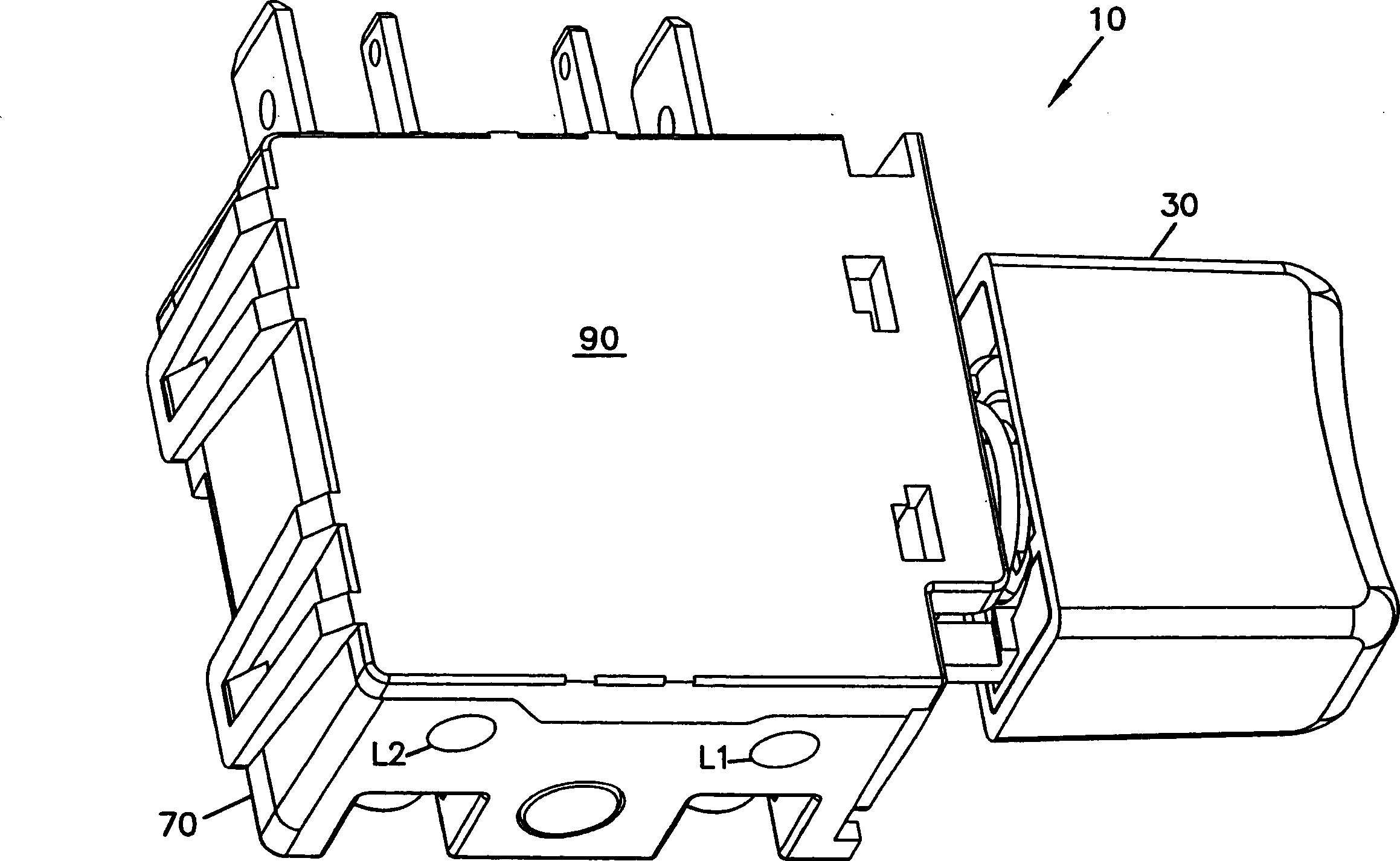
[0046]In summary, switch embodiments are configured to minimize jumping between contacts in the circuit. In the actuated position of the switch, the switch provides sufficient contact pressure between the contacts to close the circuit. Conversely, in the switch deactuated position, the switch removes all contact pressure between the contacts to open the circuit. However, while the switches below are described in terms of electrical wiring circuits, certain embodiments of the invention may be adapted for use with other known circuit configurations.

[0047] Figures 1A-1C An exemplary embodiment of switch 10 is shown including a trigger 30 movable between a switch actuated position and a switch deactuated position. Trigger 30 includes a trigger insert 34 (best seen in FIG. 3 ) which is coupled to actuator 20 (best seen in FIG. 2 ). According to one embodiment, when trigger 30 is actuated (i.e., depressed), it pushes actuator 20 toward shift bracket 40 (best seen in FIGS. 4 a...


PUM


Abstract

An apparatus and method for minimizing jumping and contact welding at a contact point includes a switch having a first contact moveable from a deactuated position of the switch to an actuated position of the switch toward a second contact and away from the The second contact moves from the actuated position of the switch back to the deactuated position of the switch. A change bracket is operable to engage the first contact and includes a trigger mechanism that contacts the first contact with the second contact and releases the first contact from the second contact. The trigger mechanism uses a switching barrier to switch between an actuated position of the switch and a deactuated position of the switch. The actuator is movable on the shift carriage to overcome the shift barrier when moving between a deactuated position of the switch and an activated position of the switch.

Description

technical field [0001] The present invention relates to a system and method for minimizing arcing and contact welding between electrical contacts in an on-off switch. In particular, the present invention relates to a circuit interrupter that produces snap action connection and disconnection between electrical contacts. Background technique [0002] Different kinds of circuits are susceptible to many adverse conditions. For example, in an on-off switch, an arc or spark can be created between the electrical contacts when paired contacts bounce or partially separate when the switch is switched to the off position. This situation is called a teasable condition in electrical systems. Also, the contacts of this electrical system can be soldered together, allowing the circuit to remain closed even after many cycles of the switch in the off position. [0003] This type of on-off switch is commonly used in triggers for manually operated equipment such as mains powered construction...

Claims


Application Information

Patent Timeline
Patent Type & Authority Applications(China)
IPC IPC(8): H01H71/10
CPCH01H1/20H01H5/045H01H9/06
Inventor 吕文凯
Owner DEFOND COMPONENTS
Learn More