Engine remote measuring early warning system

An early warning system and locomotive technology, applied in electric vehicles, vehicle components, electric vehicle charging technology, etc., can solve problems such as untimely troubleshooting, increased friction, and inaccurate barometer data

Inactive Publication Date: 2007-01-24
BEIJING TIMESBRIGHT ELECTRONICS TECH COMPANY
View PDF0 Cites 5 Cited by
  • Summary
  • Abstract
  • Description
  • Claims
  • Application Information

AI Technical Summary

Problems solved by technology

At present, the detection and early warning methods of key locomotive equipment have the following defects: ①The detection of pantograph air pressure is realized by checking the barometer, which is extremely inconvenient for the drivers and passengers in the driving state; The data is inaccurate and prone to misoperation
When the air pressure is too high, the friction between the pantograph and the high-voltage wire increases, which damages the pantograph and the wire of the locomotive; when the air pressure is too low, the pantograph and the high-voltage wire are in poor contact, causing electric sparks to damage the internal facilities of the locomotive
②When the pantograph air pressure is found to be too low, the locomotive control power supply is manually switched to the on-board power supply, resulting in failure to deal with the fault in time
③When the temperature of the main transformer is too high, the power will be cut off to stop, and there is no early warning function, which will easily cause the locomotive to stop halfway
④The lack of phase fault of the motor will only be discovered when it reaches a fairly serious level, that is, the motor is burned, and it cannot be detected and warned in real time
⑤ It is inconvenient to monitor the pressure of the brake air pipe of the locomotive, which leads to the high pressure of the brake air pipe of the locomotive causing the brakes of the locomotive to lock up, and the low pressure causes insufficient braking force

Method used


Image

  • Engine remote measuring early warning system
  • Engine remote measuring early warning system
  • Engine remote measuring early warning system

Examples


Embodiment Construction

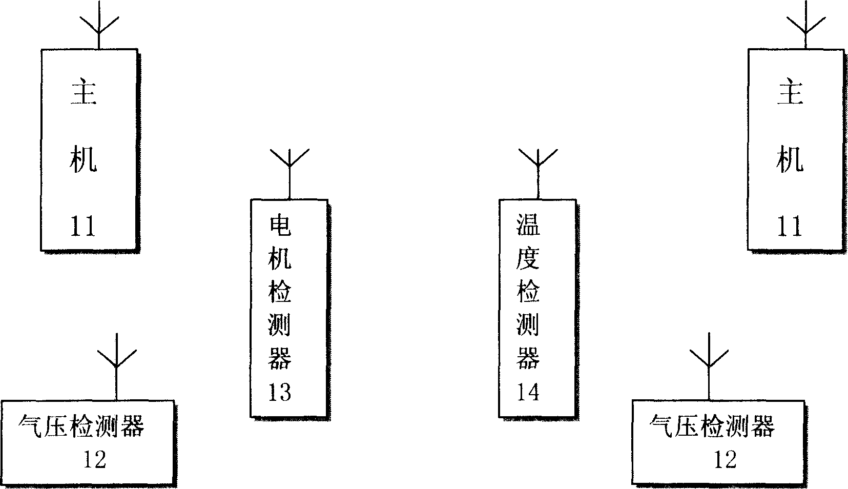
[0016] Composition of the present invention figure 1 Including: host 11, air pressure detector 12, motor detector 13, temperature detector 14 composition.

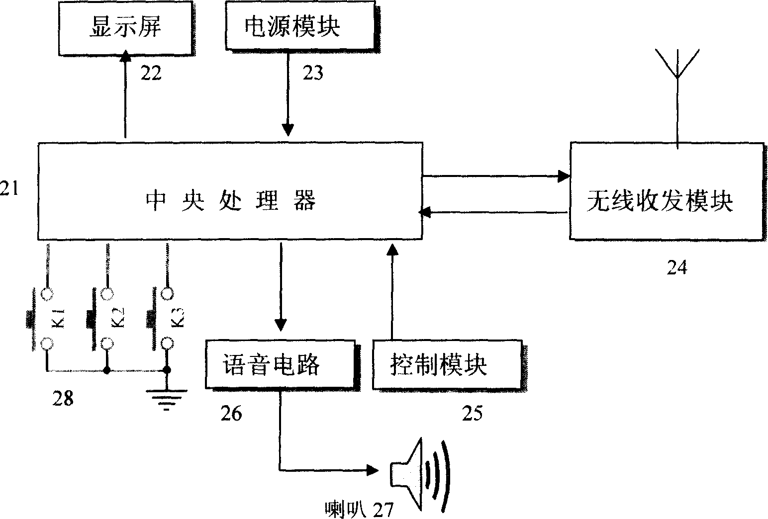
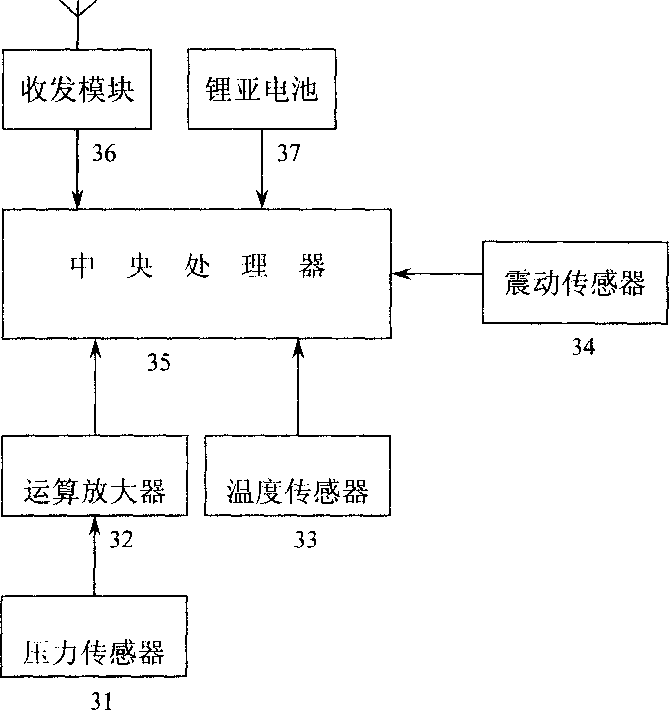
[0017] The technical scheme of the present invention comprises main engine 11, air pressure detector 12, motor detector 13, temperature detector 14; Main engine 11 is respectively installed in locomotive first, second cab; Install an air pressure detector 12 on the top, install a motor detector 13 on each motor, and install a temperature detector 14 on the main transformer; Real-time detection of the air pressure, temperature, and motor failure of the locomotive equipment, and wirelessly transmit the corresponding data to the hosts 11 in the two cabs; when a certain locomotive equipment exceeds the normal value, the two hosts 11 will issue corresponding voice prompts , digital display; when the pantograph air pressure is too low, the host 11 will automatically switch the power supply of the locomotive; the host 11 can rea...


PUM


Abstract

The present invention belongs to the field of electronic information technology, and is especially one engine remote measuring and early warning equipment. The engine remote measuring and early warning equipment consists of system units in the first and the second operator's cabins, air pressure detectors mounted separately on the pantographs and wind pump pipes, motor detectors mounted separately on the motors, and one temperature detector mounted on the main transformer. All the parts operate automatically for real-time detection of the air pressure, temperature, etc; and the detected data are transmitted to the system units. In case of some fault, the system units will send corresponding phonetic prompt and digital display. The system units may realize bidirectional communication with other railway equipment to ensure the optimal engine performance and the safety.

Description

technical field [0001] The invention relates to a locomotive telemetry and early warning system, which belongs to the field of electronic information and is a multifunctional device for improving the safety performance of existing railway locomotives. Background technique [0002] The development speed of China's railway has occupied the first place in the world, but it still fails to meet the needs of national economic development. Therefore, China Railway has proposed a high-speed, heavy-duty development strategy. Under the premise of continuous speed increase and loading, in order to ensure the safe production of railway transportation, it is necessary to carry out more reliable monitoring, prompt and early warning of the key equipment of the locomotive. At present, the detection and early warning methods of key locomotive equipment have the following defects: ①The detection of pantograph air pressure is realized by checking the barometer, which is extremely inconvenient...

Claims


Application Information

Patent Timeline
Patent Type & Authority Applications(China)
IPC IPC(8): B60L3/04
CPCY02T90/16
Inventor 朱肃生
Owner BEIJING TIMESBRIGHT ELECTRONICS TECH COMPANY
Why Eureka
Try Eureka