
Joint of mould plate supporting and locating device for wall building and mould plate supporting and locating device for wall building

A positioning device and formwork support technology, which is applied in the connection of formwork/formwork/work frame, the preparation of building components on site, construction, etc., can solve the problems affecting the anti-leakage performance of the wall

Inactive Publication Date: 2007-01-31
张发裕
View PDF0 Cites 0 Cited by
  • Summary
  • Abstract
  • Description
  • Claims
  • Application Information

AI Technical Summary

Problems solved by technology

The current formwork support and positioning device often uses U-shaped steel bars corresponding to the thickness of the wall between the formwork on both sides to determine the distance between the formwork, and then sets the connecting screw through the formwork on both sides, and uses nuts and gaskets outside the formwork on both sides. The parts are connected with the screw to position the formwork, and the part between the formwork on both sides is covered with pipes. When the wall is poured, the connecting screw is pulled out from the pipe, but the pipe cannot be taken out and remains in the wall. Form a through hole through the wall, even if the hole is filled later, it will still affect the anti-leakage performance of the wall

Method used


Image

  • Joint of mould plate supporting and locating device for wall building and mould plate supporting and locating device for wall building
  • Joint of mould plate supporting and locating device for wall building and mould plate supporting and locating device for wall building

Examples


Embodiment Construction

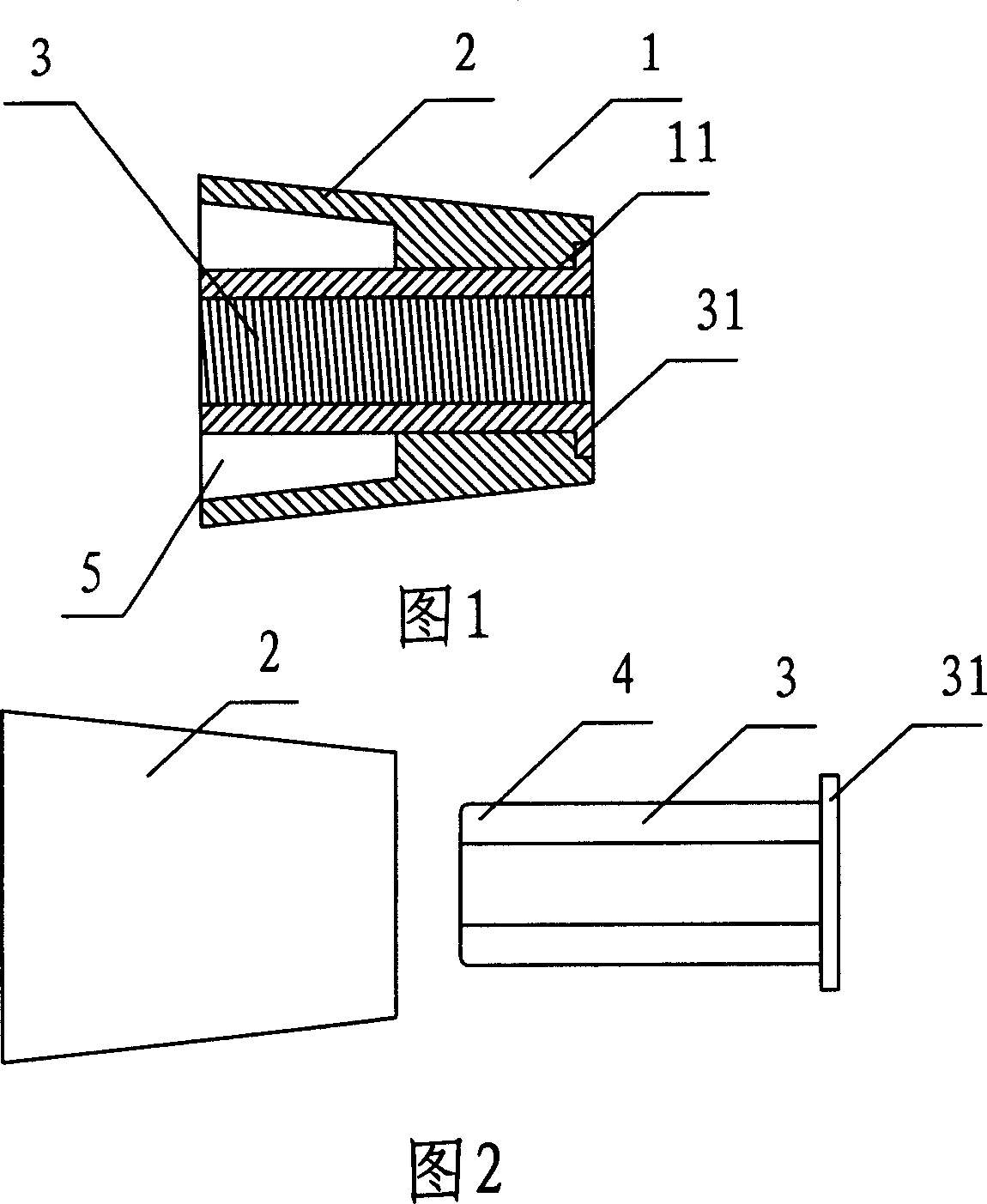
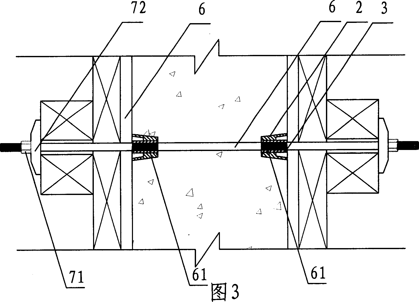
[0009] Refer to accompanying drawings 1 and 2. The joint 1 of the formwork supporting and positioning device for building walls provided by the present invention includes a tapered outer sleeve 2 and a central threaded connecting pipe 3. The head of the threaded connecting pipe has a connection shape 4 matched with the tool, and the head of the central threaded connecting pipe is connected to the Between the jackets there is a space 5 for tools to penetrate.

[0010] The central threaded connecting pipe is separated from the tapered outer casing, so that the joint can be more convenient to manufacture, and the outer casing 2 and the central threaded connecting pipe 3 are made of different materials. For example, the central threaded connecting pipe 3 is made of a metal material. The tapered housing is made of inexpensive plastic, reducing the manufacturing cost of the joint. The tapered jacket is provided with a central stepped hole 11, and the central threaded connecting pip...


PUM


Abstract

This invention provides a kind of joint of the building form board supporting fixing location device. It includes the cone cover and the centre thread connecting pipe, the head of the thread connecting pipe is in the connection shape which matches the implement, there is space between the head of the centre thread connecting pipe and cover, which can be for an implement entering. The joint provided in this invention is able to be dismantled after the building of wall body is finished, and the centre screwed hole can be bridge connection of the supporting and fixing structure inside and outside the form board, it is convenient for the structure of the supporting and fixing device to be optimization and proper, to make the wall body won't be through-hole after the supporting and fixing device being dismantled. The said centre thread connecting pipe is divided with the cone cover, the cone cover sets centre stepped hole, centre thread connecting pipe is inserted in the stepped hole and it sets the boss which matches the stepped hole. This invention also provides a kind of building form board supporting fixing location device. It includes a pair of the said joint, it also includes the centre rod which links the said pair of joint, both ends of the centre rod has the thread matches the centre thread connecting pipe, it includes the external screw which connect the gas thread of the centre thread connecting pipe.

Description

technical field [0001] The invention relates to a formwork supporting and positioning device for building concrete walls and its accessories. Background technique [0002] When building a cast-in-place concrete wall, it is necessary to use a formwork support positioning device to position the formwork on both sides according to the design spacing, so that the wall poured between the formwork meets the design thickness. The current formwork support and positioning device often uses U-shaped steel bars corresponding to the thickness of the wall between the formwork on both sides to determine the distance between the formwork, and then sets the connecting screw through the formwork on both sides, and uses nuts and gaskets outside the formwork on both sides. The parts are connected with the screw to position the formwork, and the part between the formwork on both sides is covered with pipes. When the wall is poured, the connecting screw is pulled out fr...

Claims


Application Information

Patent Timeline
IPC IPC(8): E04G17/00E04G17/065
Inventor 张发裕
Owner 张发裕
Learn More