a dispenser

A technology of liquid separator and filter screen support, which is applied in the direction of refrigeration and liquefaction, refrigeration components, refrigerators, etc., and can solve problems such as compressor abnormal shock, exhaust pipe shock, compressor liquid shock, etc., to prevent liquid shock Occurrence, improvement of reliability, and effect of reducing liquid hammer phenomenon

Active Publication Date: 2018-06-26
ZHUHAI GREE REFRIGERATION TECH CENT OF ENERGY SAVING & ENVIRONMENTAL PROTECTION
View PDF8 Cites 0 Cited by
  • Summary
  • Abstract
  • Description
  • Claims
  • Application Information

AI Technical Summary

Problems solved by technology

[0004] However, when the existing liquid distributor included two or more exhaust pipes, the air inlet of the exhaust pipe would have a larger direct facing area with the through hole on the filter screen support, so that the liquid separator There are at least the following problems in the compressor: during the operation of the compressor, when the refrigerant entering the cylinder from the suction pipe contains more liquid refrigerant, the liquid refrigerant can directly enter the exhaust pipe through the through hole on the filter screen bracket , will cause impact on the exhaust pipe; and when a large amount of liquid refrigerant enters the cylinder of the pump body with the gaseous refrigerant, it will cause abnormal impact accidents on the compressor, thereby causing the compressor to experience liquid shock

Method used


Image

  • a dispenser
  • a dispenser
  • a dispenser

Examples


Embodiment 1

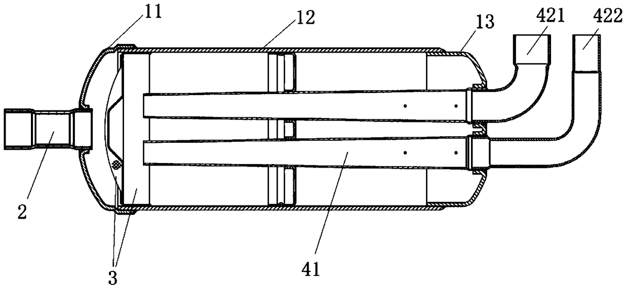
[0034] Such as figure 1 , figure 2 and image 3 As shown, this embodiment provides a liquid dispenser, specifically, the liquid dispenser includes a cylinder body, a suction pipe 2, a filter assembly 3 and at least two exhaust pipes. Wherein, the cylinder includes an upper cylinder 11 , a middle cylinder 12 and a lower cylinder 13 . The suction pipe 2 is connected to the top end of the cylinder (that is, the suction pipe 2 is connected to the end of the upper cylinder 11 ), and is used to transport the refrigerant into the cylinder. The filter screen assembly 3 is arranged in the cylinder, preferably located in the middle cylinder 12 and close to the upper cylinder 11 . The filter screen assembly 3 includes a filter screen and a filter screen support 31 , the filter screen is installed on the filter screen support 31 for filtering the refrigerant entering the cylinder through the suction pipe 2 and promoting liquid separation of the refrigerant. The screen support 31 is p...

Embodiment 2

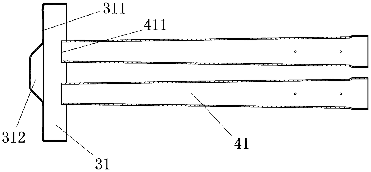
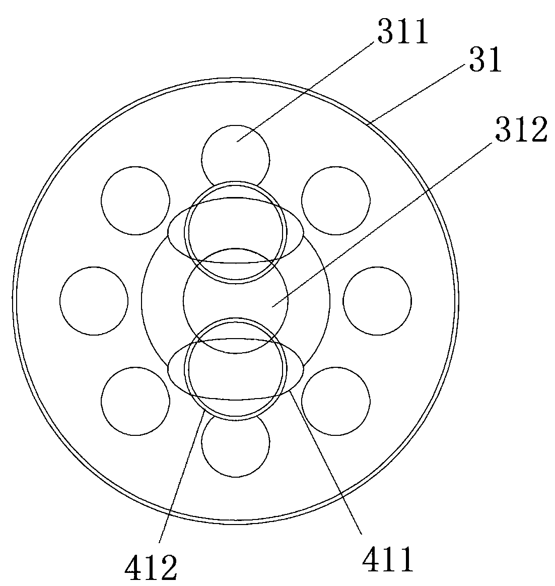
[0039] Preferably, this embodiment provides a liquid dispenser, compared with the previous embodiment, such as figure 2 and image 3 As shown, in this embodiment, a protrusion 312 is provided at the center of the filter screen support 31 . Wherein, a plurality of through holes 311 are evenly distributed around the protrusion 312 . Preferably, the filter screen support 31 in this embodiment is circular, and the distances from the plurality of through holes 311 to the center of the filter screen support 31 are equal.

[0040] Preferably, if figure 2 and image 3 As shown, in this embodiment, the air inlet 411 of the exhaust inner pipe 41 is set facing the area between the center of the filter screen support 31 and the through hole 311 . Here, in order that there is no facing area between the air inlet 411 of the exhaust inner pipe 41 and the through hole 311, the three schemes described in Embodiment 1 can also be adopted for the exhaust inner pipe 41 or the filter screen ...

Embodiment 3

[0043] Preferably, this embodiment provides a liquid dispenser, compared with Embodiment 2, such as Figure 2 to Figure 5 As shown, in this embodiment, the shape of the air inlet 411 of the exhaust inner pipe 41 is improved, and it is set as an ellipse. Such as image 3 As shown, there is no direct facing area between the air inlet 411 and the through hole 311 on the screen holder 31 after being arranged in an oval shape.

[0044] In the prior art, the air inlets of the exhaust pipes are all circular in shape. On the premise of ensuring that the area of ​​the air inlets meets the conditions, the circular air inlets of the exhaust pipes of the liquid separators of the multiple exhaust pipes are all the same as the There is a facing area in the through hole on the filter screen support. Compared with the existing technology, such as figure 2 and image 3 As shown, the liquid separator provided in this embodiment avoids the existence of the air inlet 411 of the exhaust inner p...


PUM


Abstract

The invention relates to a liquid separator, and relates to the technical field of liquid separators. According to the main technical scheme, the liquid separator comprises a barrel body, an air absorbing tube, a filter screen assembly and at least two exhausting tubes, wherein the air absorbing tube is connected to the top end of the barrel body; the filter screen assembly is mounted in the barrel body, comprising a filter screen and a filter screen bracket; a plurality of through holes are formed in the filter screen bracket; each exhausting tube is connected to the bottom end of the barrel body, and each exhausting tube comprises an inner exhausting tube which is arranged in the barrel body and positioned below the filter screen bracket; the direct-facing area between an air inlet of each inner exhausting tube and each through hole in the filter screen bracket is avoided. The liquid separator is mainly used for decreasing the quantity of liquid refrigerants which directly enter the exhausting tubes through the through holes in the filter screen bracket, thus the impact vibration of the liquid refrigerants on the exhausting tubes and a compressor can be reduced, the liquid impact can be prevented, and as a result, the running reliability of the compressor can be improved.

Description

technical field [0001] The invention relates to the technical field of a liquid dispenser, in particular to a liquid dispenser. Background technique [0002] The liquid separator can separate the gas-liquid mixture from the evaporator, the separated gas enters the compressor through the exhaust pipe of the liquid separator, and the separated liquid is stored at the bottom of the liquid separator. Therefore, the main function of the liquid separator is to prevent the liquid refrigerant from directly entering the compressor, thereby preventing the occurrence of a large number of liquid hammer problems. [0003] The existing liquid distributor mainly includes a cylinder, a suction pipe for delivering refrigerant to the cylinder of the liquid distributor, an exhaust pipe for delivering the gaseous refrigerant after liquid separation in the cylinder to the compressor, and a pipe installed in the cylinder. The filter assembly in the body is used to filter the refrigerant and prom...

Claims


Application Information

Patent Timeline
Patent Type & Authority Patents(China)
IPC IPC(8): F25B43/00
CPCF25B43/00F25B43/003
Inventor 白璐琛赵旭敏彭慧明韩鑫金冀龙樊峰刚金鹏程
Owner ZHUHAI GREE REFRIGERATION TECH CENT OF ENERGY SAVING & ENVIRONMENTAL PROTECTION
Why Eureka
Try Eureka