Supercharge Your Innovation With Domain-Expert AI Agents!

Image forming apparatus

An image and image information technology, applied to the electrical recording process using the charge pattern, the equipment and instruments of the electric recording process using the charge pattern, etc., can solve the problem of protracted implementation time

Inactive Publication Date: 2007-01-31
RICOH KK
View PDF3 Cites 12 Cited by
  • Summary
  • Abstract
  • Description
  • Claims
  • Application Information

AI Technical Summary

Problems solved by technology

This will result in prolongation of the implementation time of the adjustment control of the image production conditions.

Method used


Image

  • Image forming apparatus
  • Image forming apparatus
  • Image forming apparatus

Examples


Embodiment Construction

[0081] Embodiment of the invention

[0082] Hereinafter, a first embodiment of a so-called tandem full-color electrostatic image forming apparatus provided with a plurality of photoreceptors (hereinafter referred to as “image forming apparatus”) as an image forming apparatus to which the present invention is applied will be described.

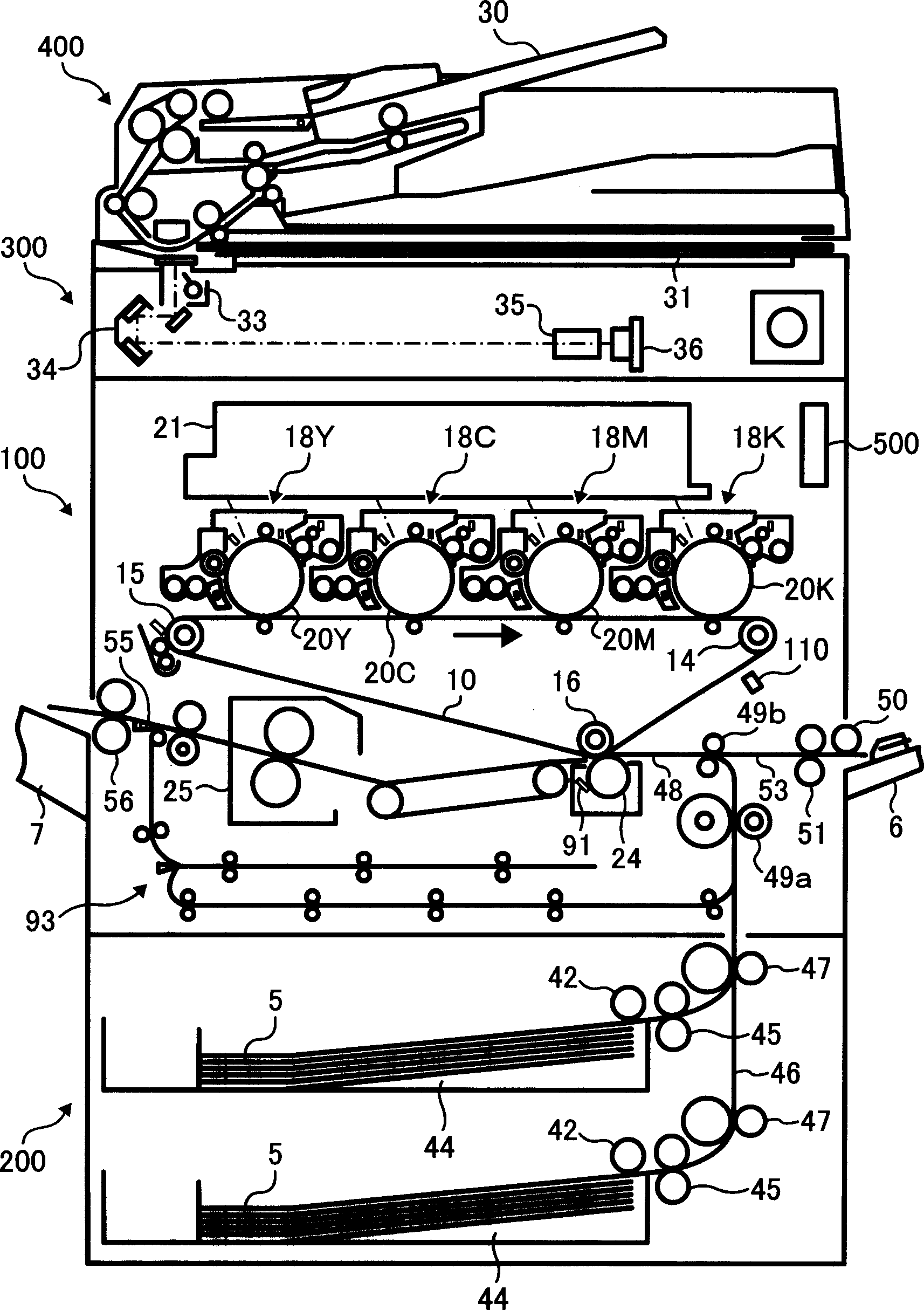
[0083] First, the basic structure of the image forming apparatus according to the first embodiment of the present invention will be described. figure 2 is a schematic diagram of the configuration of the image forming apparatus according to the first embodiment of the present invention. In this figure, the image forming apparatus includes:

[0084] There is a printing section 100 for image formation;

[0085] A paper supply device 200 that is installed below the printing section and supplies transfer paper 5 as a recording member to the printing section 100;

[0086] A scanner 300 installed on the printing unit 100 to read document images; a...


PUM


Abstract

An image forming apparatus includes an image carrying member, an image forming mechanism, an optical sensor, and a controller. The image forming mechanism performs an image forming operation for forming a reference toner image on the image carrying member under a specific setting associated with the image forming mechanism. The optical sensor is arranged in a vicinity to the image carrying member. The controller performs an optical toner test for checking, by using the optical sensor, optical characteristics of the reference toner image formed on the image carrying member and to adjust the specific setting based on a result of the optical toner test.

Description

technical field [0001] The present invention relates to an image forming apparatus such as a copier, a printer, and a facsimile that adjusts and controls conditions for forming a toner image at a predetermined timing. Background technique [0002] Until now, adjustment and control of image creation conditions have been performed based on the existence or non-existence of predetermined conditions, such as whether it is immediately after the power is turned on, or whether the number of printed sheets has reached a predetermined number. For example, Japanese Patent Laid-Open No. 9-284556, Japanese Patent Laid-Open No. 2002-236402, Japanese Patent No. 2004-354623, and Japanese Patent No. 3500008 disclose image forming apparatuses using these techniques. In the adjustment control of such image making conditions, for example, at first, the light emitted by the optical sensor light emitting device (such as LED) is reflected on the surface of the photoreceptor as the latent image ca...

Claims


Application Information

Patent Timeline
Patent Type & Authority Applications(China)
IPC IPC(8): G03G15/00G03G15/08
CPCG03G2215/00042G03G15/5033G03G15/5058
Inventor 石桥均有泉修小林信二小林一三内田福年榎并崇史森本亮太长谷川真加藤真治藤森仰太竹内信贵田中加余子平山裕士渡辺直人
Owner RICOH KK
Features
  • R&D
  • Intellectual Property
  • Life Sciences
  • Materials
  • Tech Scout
  • Unparalleled Data Quality
  • Higher Quality Content
  • 60% Fewer Hallucinations
Learn More