Electricity enhancing original position restoring for contaminated soil

A technology for electrical remediation, soil, applied in the field of electrical enhanced in situ remediation

Inactive Publication Date: 2007-02-07
AURORA HLDG BV
View PDF3 Cites 11 Cited by
  • Summary
  • Abstract
  • Description
  • Claims
  • Application Information

AI Technical Summary

Problems solved by technology

However, using electric current from electrodes to heat the soil has its problems
In this case, boiling near the electrodes may be a problem

Method used


Image

  • Electricity enhancing original position restoring for contaminated soil
  • Electricity enhancing original position restoring for contaminated soil
  • Electricity enhancing original position restoring for contaminated soil

Examples


Embodiment Construction

[0041] These and other objects and advantageous aspects of the present invention will be elucidated below with reference to the diagrams as described above.

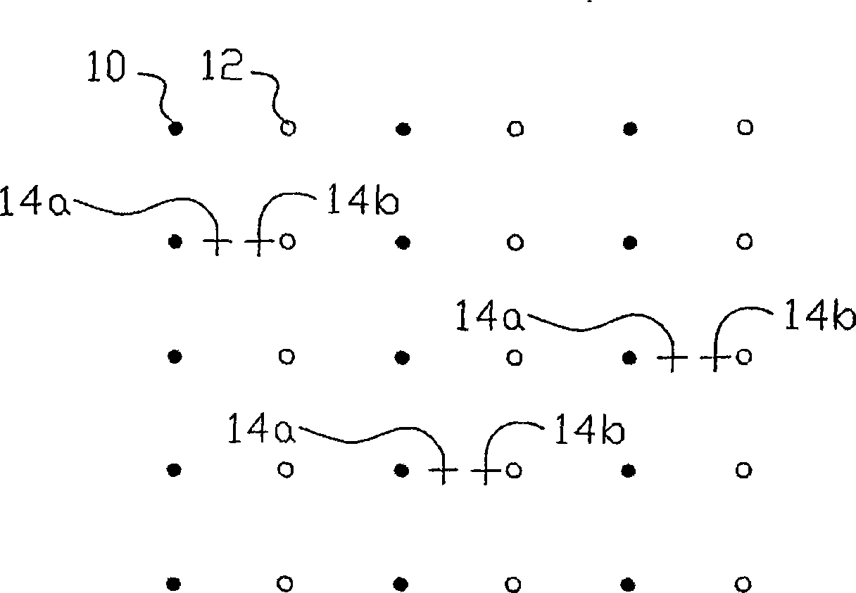
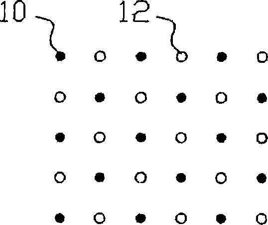
[0042] Figure 1a , b shows part of an array of cathodes 10 (marked with solid circles) and anodes 12 (marked with open circles) inserted in the soil of a land area. Figure 1a It is shown that alternating rows of anodes and rows of cathodes may be used. Figure 1b It is shown that a matrix of cathodes 10 can be used, with each anode 12 located between four cathodes 10 . Figure 1a In addition to the anode and cathode, a pair of detection electrodes 14a,b is shown inserted in the soil at selected positions such that a voltage difference between the anode and cathode results in a voltage drop between a pair of detection electrodes . For clarity, in Figure 1b These probing electrodes are omitted in , but it should be understood that the Figure 1b These electrodes can also be used in the layout.

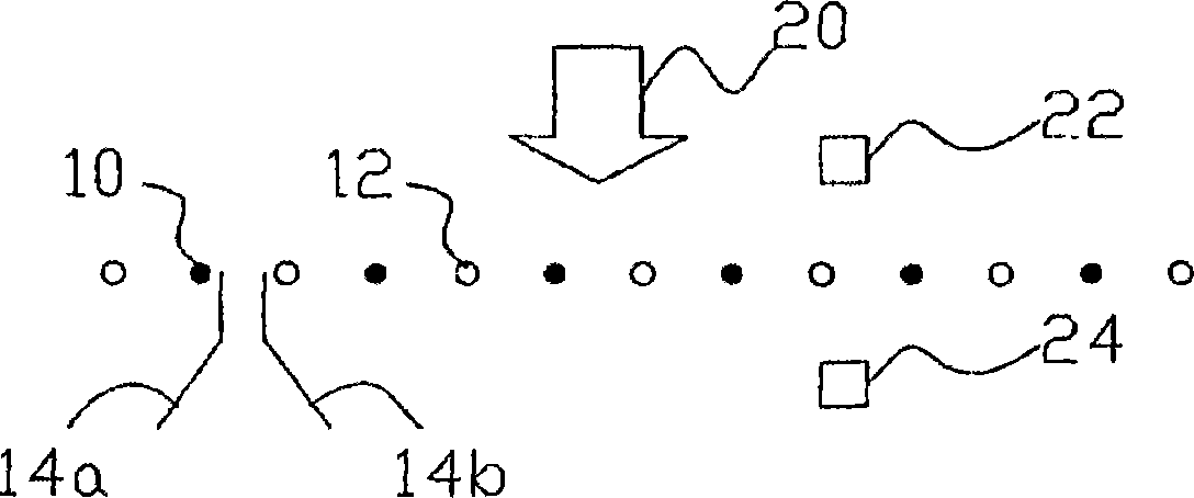
[0043] figure 2 An ...


PUM


Abstract

During in situ electroremediation of soil electric fields generated by electrodes (10, 12) that are located in the soil are used to move contamination, complexing agents, chemical reagents and / or nutrients through soil or to heat the soil. Control of the voltages and / or currents on or through the electrodes (10, 12) is used to prevent electrode clogging problems, to reduce unnecessary power consumption and / or to prevent boiling. In one aspect (electrokinetic remediation and electro heating) the current through selected electrodes (10, 12) is temporarily stepped down if the onset of clogging and or boiling is detected from an increase in the electrical resistances from an electrode into the soil. Preferably an effect of soil resistivity changes on the detection is removed by using sensing electrodes (14a, 14b) in the soil. In another aspect (elektrokinetic (bio) fence / screen) the voltage or current is adapted dependent on measured groundwater flow speed changes, so that the method remains effective with minimum power consumption. In yet another aspect (electrokinetic phyto remediation) polarity reversals of the current are timed using cumulative current measurements.

Description

technical field [0001] The present invention relates to electrically enhanced in situ remediation methods of contaminated soil. The invention further relates to systems and devices using such methods. Background technique [0002] U.S. Patent No. 5,433,829 to the same inventor as the present invention (incorporated herein by reference) describes a method of electroremediation that involves the in situ induction of unwanted ions (ionic complexes or charged particles) under the influence of an electric field. movement and through the soil. This can be achieved by inserting grids of anodes and cathodes in the ground, or when there is groundwater movement, by inserting alternating anode screens transverse to the direction of groundwater flow. Similar techniques are described in US 5,589,056 and US 5,846,393. [0003] Other electroremediation techniques (not described in US Patent No. 5,433,829) include electrically enhanced phyto-remediation and bio-reclam...

Claims


Application Information

Patent Timeline
Patent Type & Authority Applications(China)
IPC IPC(8): B09C1/08B09C1/10B09C1/06B09C1/00
CPCB09C1/10B09C1/002B09C1/06B09C1/085B09C1/105
Inventor 维伯瑞恩·波尔
Owner AURORA HLDG BV
Why Eureka
Try Eureka