
An optical data disc with multiple booting points

A technology for data discs and optical discs, which is applied to data recording, multi-layer discs, disc-shaped record carriers, etc.

Inactive Publication Date: 2007-02-07
KONINKLIJKE PHILIPS NV
View PDF0 Cites 0 Cited by
  • Summary
  • Abstract
  • Description
  • Claims
  • Application Information

AI Technical Summary

Problems solved by technology

This will result in a huge overhead in certain applications
Also, it may result that a particular application will spend a considerable amount of time performing tasks that have no or limited relevance to that particular application

Method used


Image

  • An optical data disc with multiple booting points
  • An optical data disc with multiple booting points
  • An optical data disc with multiple booting points

Examples


Embodiment Construction

[0018] This part describes in detail one of the best ways to implement the present invention.

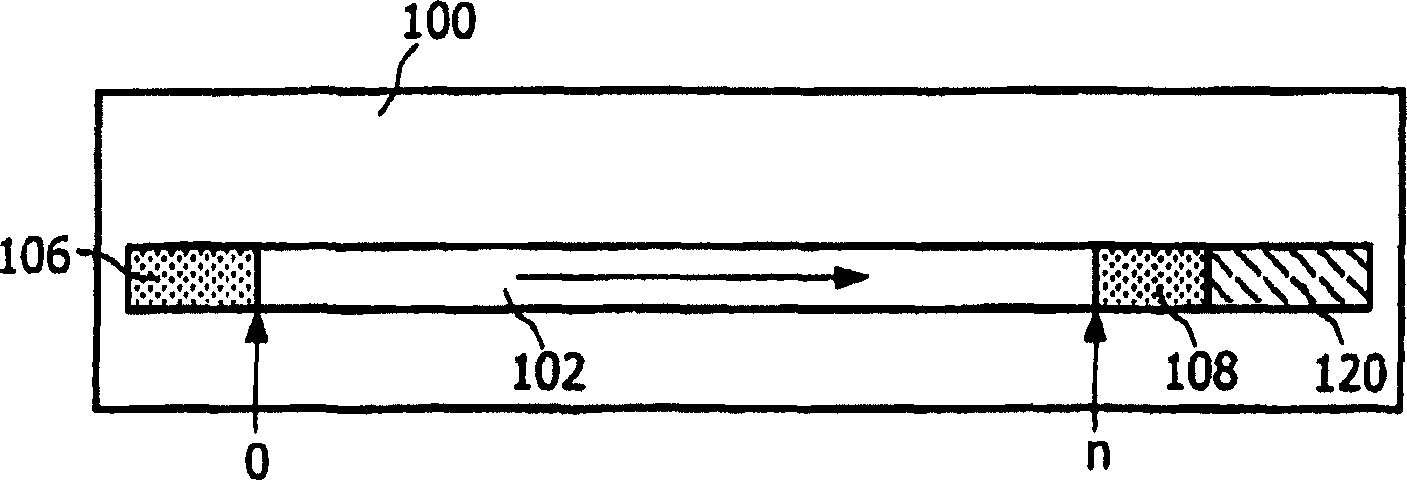
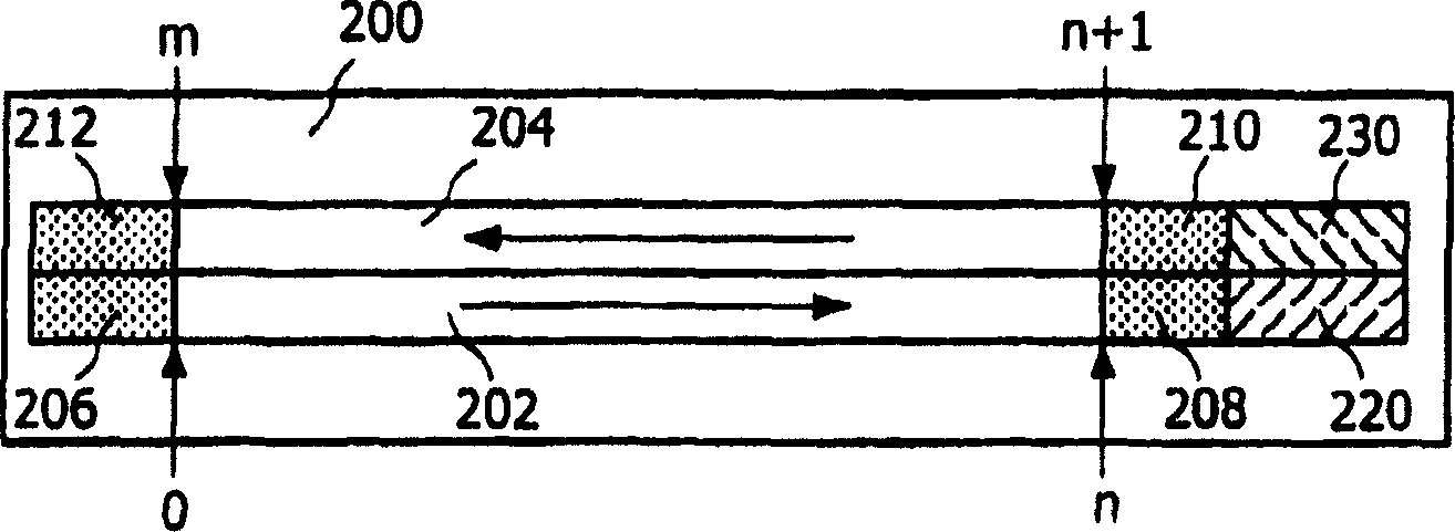
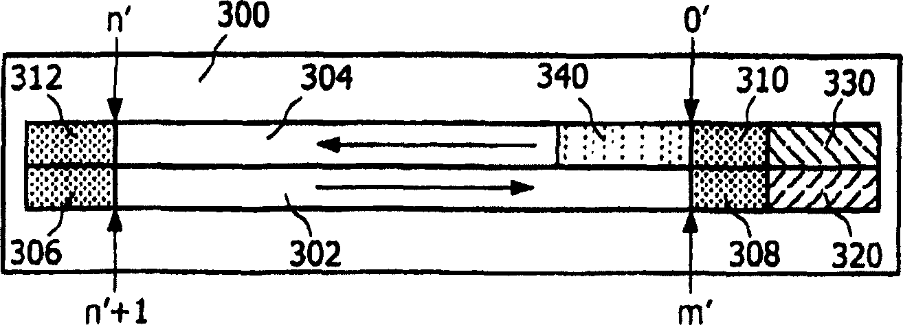
[0019] Figure 1 shows a (prior art) single-layer Portable Blu-ray Disc 100 (PB) with a single boot entry point. The boot entry point typically physically resides in the lead-in area 106 of the optical data layer 102 . The lead-in area 106 generally includes a disc navigation area (DN) and a rights management area (RM). PB 100 also includes a lead-out area 108 and a RIM 120 . An area on the PB 100 that is typically used for an application mapped as a logical address space starts with a logical address "0" immediately following the lead-in area 106 and ends with "n" up to the front of the lead-out area 108 . Typically, the reading direction of data is from the lead-in area 106 towards the lead-out area 108 (arrow direction), since optical discs are typically read and written in an outward (data) spiral. The lead-in area 106 is usually located near the inner hole of the disc, while ...


PUM


Abstract

The boot process can take a long time, and it usually starts with the lead-in area of ​​the main data layer of an optical data disc. A Portable Blu-ray (PB) disc as a dual-boot disc includes a second data layer (304) from which an application-specific optical drive can boot directly. The dual boot disk still complies with PB prior art standards for conventional applications. This second boot (340) will shorten the boot time for certain applications and will make the application software smaller, which is especially relevant for gaming, portable devices and related certain applications.

Description

technical field [0001] The present invention relates to the boot process of optical discs. In particular, the present invention relates to disc formats capable of multiple booting from a single disc. [0002] Furthermore, the present invention relates to a system, an apparatus and an application that allow the use of one optical disc to support multiple boot entry points. [0003] The invention is particularly relevant to applications requiring a simple and fast loading and booting process, especially from multilayer optical data discs. Background technique [0004] Existing standards for optical discs allow for a single boot format on one disc. Typical dual-layer disk applications map the address space of the second layer contiguously from the end of the first layer. A single boot process starting on the inside of the first layer loads both layers. Layer transitions are usually transparent to the application. [0005] The existing mapping of the second layer is very su...

Claims


Application Information

Patent Timeline
Patent Type & Authority Applications(China)
IPC IPC(8): G11B27/10G06F9/445
CPCG11B2220/2591G11B27/105G11B2220/235G11B20/12G11B27/10G11B7/007
Inventor W·F·J·方蒂恩
Owner KONINKLIJKE PHILIPS NV
Learn More