Apparatus and method to minimize arcing between electrical connectors

一种连接器件、电弧的技术,应用在用于限制过电流/过电压的紧急保护电路装置、电池电路装置、连接装置的零部件等方向,能够解决操作员人身伤害、连接器焊接或熔化、部件损害等问题

Inactive Publication Date: 2007-02-07
TE CONNECTIVITY CORP
View PDF2 Cites 10 Cited by
  • Summary
  • Abstract
  • Description
  • Claims
  • Application Information

AI Technical Summary

Problems solved by technology

Depending on the design and construction of the system, arcing can cause severe damage to components (such as pitting), or can cause soldering or melting of connectors when their pins are melted by the arc
Also, in many systems, voltage and current levels are high enough to cause personal injury to operators attempting to connect or disconnect lines under load

Method used


Image

  • Apparatus and method to minimize arcing between electrical connectors
  • Apparatus and method to minimize arcing between electrical connectors
  • Apparatus and method to minimize arcing between electrical connectors

Examples


Embodiment Construction

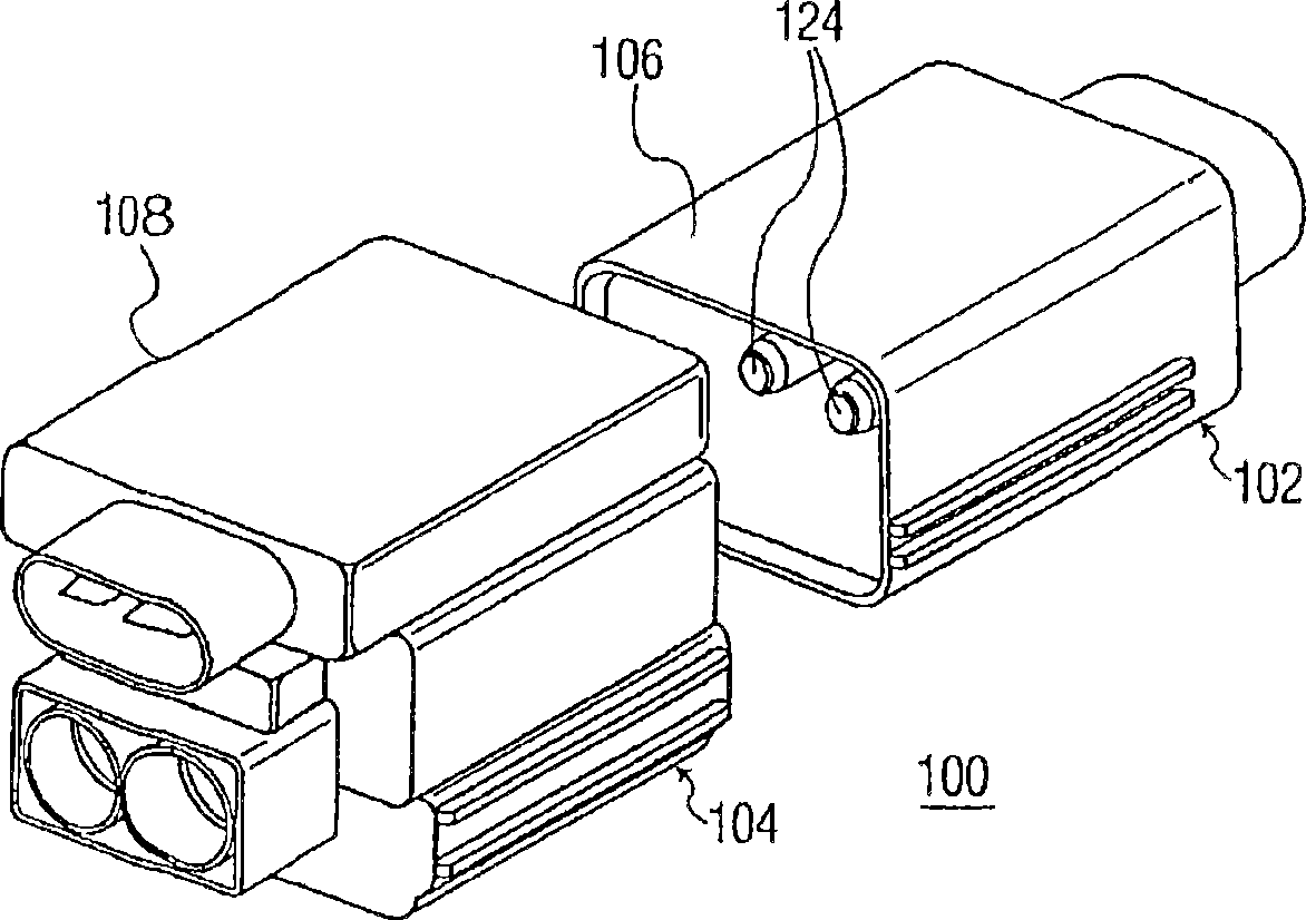
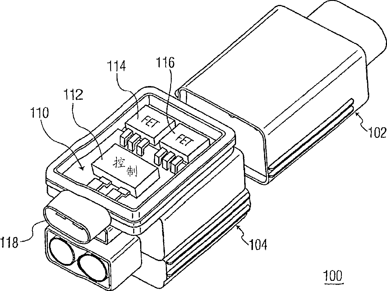
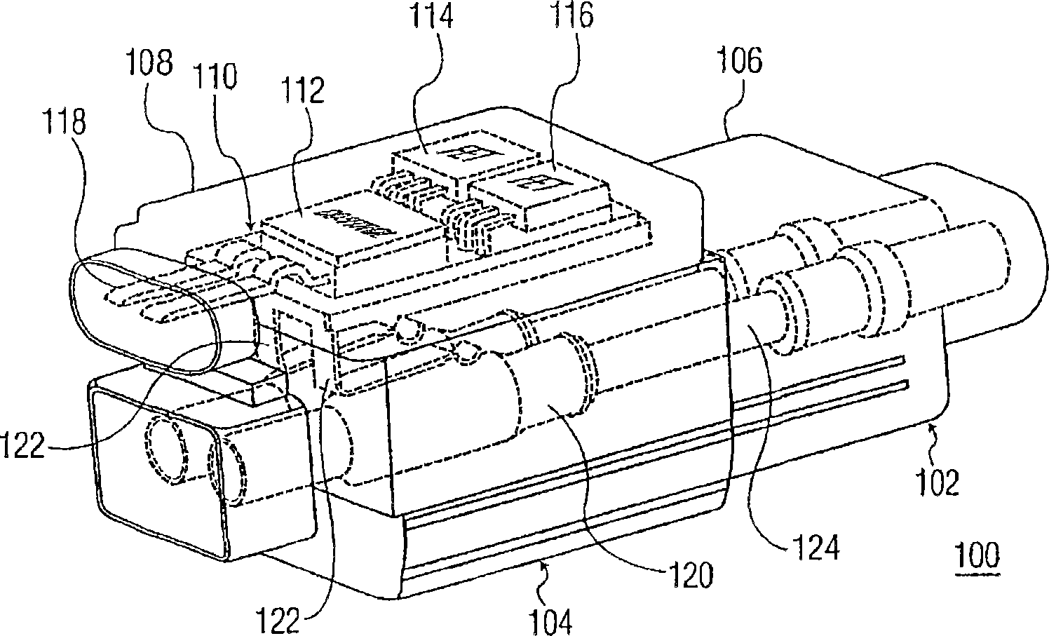
[0015] Now referring to the drawings in detail, in several views, the same reference numerals indicate the same elements throughout. figure 1 An electrical connector 100 according to an embodiment of the present invention is shown in FIG. It may include two mating halves 102,104. As shown, one half 102 may include a housing 106 and a pair of connector pins 124. The illustrated embodiment is an example of a connector intended for use in automobiles or similar applications, where it can be found that the connector carries a very large current. However, it should be understood that the present invention is not limited to connectors, but can be used with any device (such as a relay, etc.) that can be engaged / detached in a similar manner. in figure 1 The connector illustrated in may also include a second mating half 104, which is active, and also includes a housing 108, which contains an arc suppression circuit according to an embodiment of the present invention, which will be descri...


PUM


Abstract

The present invention discloses an electrical connection device (100) and method for minimizing arcing when the connection device is connected or disconnected under load. The present invention provides an arc suppression circuit in which one or more regulators (114, 116), such as transistors, are integrated into the connection device housing, the arc suppression circuit senses movement of the connection device, and when sensed Shunts current into impedance circuits when a possible arc condition is detected.

Description

Technical field [0001] The present invention generally relates to an electrical connector assembly. In particular, the present invention relates to an electrical connector including components for preventing or at least minimizing the occurrence of arc discharge. Background technique [0002] Electrical connectors provide electrical paths or connection points to provide mechanical connections between wires, circuit leads, components, or other current-carrying devices. Generally, electrical connectors are connected or disconnected during periods when no current is passing through the device. Although generally not recommended, electrical connectors can be connected or disconnected under load based on voltage or current levels. This may in turn lead to an arc discharge state, where the current jumps over the air gap between the contacts. Depending on the design and structure of the system, arc discharge may cause severe damage to components (such as pitting), or may cause the conne...

Claims


Application Information

Patent Timeline
Patent Type & Authority Applications(China)
IPC IPC(8): H02J7/00H01R13/53H01R13/703H01R13/713H01R31/06H02H9/00
CPCH01R13/53H02H9/004H01R13/713H01R13/7032H01R31/065
Inventor 莱尔·S·布赖恩杰里米·C·佩特森埃德温·G·科克斯
Owner TE CONNECTIVITY CORP
Why Eureka
Try Eureka