PTC current limiting device having molding part made of insulating material

A technology of current limiting device, insulating material, applied in the direction of resistors with positive temperature coefficient, resistors with current response, covering/lining, etc., can solve problems such as inability to eliminate arcs, shortening, and inability to expect noise reduction

Active Publication Date: 2006-07-19
LG CABLE LTD (KR) +1
View PDF1 Cites 4 Cited by
  • Summary
  • Abstract
  • Description
  • Claims
  • Application Information

AI Technical Summary

Problems solved by technology

[0008] Therefore, the conventional current limiting device aims to increase the contact pressure by using the extrusion structure to control the surface area of ​​the first electrode 2, 3 and the second electrode 4, 5, but cannot avoid the Arc generation caused by electron repulsion energy and time difference in resistance generated in the electric arc, and it is not easy to avoid deterioration of current limiting characteristics and flashover between electrodes due to the generated arc
[0009] In addition, the frames 6, 7 proposed in the prior art, which are made of insulating material and install

Method used


Image

  • PTC current limiting device having molding part made of insulating material
  • PTC current limiting device having molding part made of insulating material
  • PTC current limiting device having molding part made of insulating material

Examples


Embodiment Construction

[0035] Preferred embodiments of the present invention will be described in detail below with reference to the accompanying drawings. It should be understood prior to the description that the terms used in the specification and appended claims should not be construed as limited to the ordinary and dictionary meanings, but should be on the basis of allowing the inventor to appropriately define the terms to best illustrate this principle , to be interpreted based on the meanings and concepts corresponding to the technical aspects of the present invention. Therefore, the description made here is only a preferred example for the purpose of illustration, and is not intended to limit the scope of the present invention, so it should be understood that other equivalents and replacements can be made without departing from the spirit and scope of the present invention Revise.

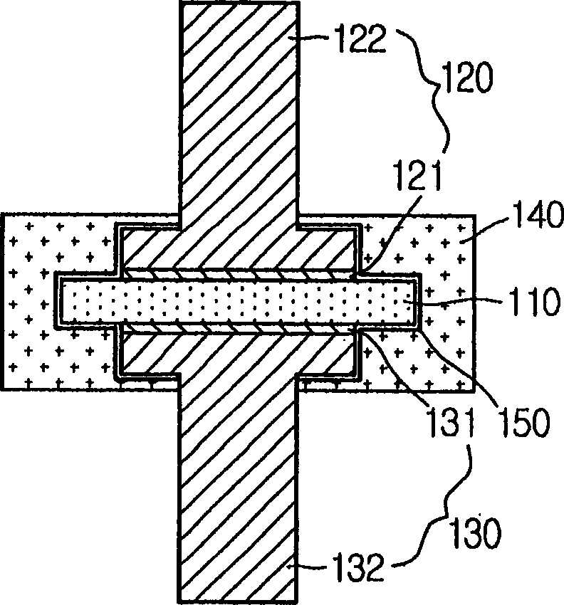
[0036]figure 2 is a sectional view showing a PTC (Positive Temperature Coefficient) current limiting device ac...


PUM


Abstract

Disclosed is a PTC (Positive Temperature Coefficient) current limiting device for limiting a current by use of PTC characteristics, which includes a PTC element having the PTC characteristics; a pair of electrode units arranged on both sides to face each other with the PTC element being interposed therebetween; and a molding part prepared around the PTC element and the electrode units to surround at least an interface region between the PTC element and the electrode units, the molding part being made of elastic insulating material. The molding part is made of an elastic insulating material or any insulating materials selected from vacuum, gas and oil. Thus, this device may effectively restrain an arc generated while limiting overcurrent or short circuit current, and also prevent flashover between electrodes.

Description

technical field [0001] The present invention relates to a PTC (Positive Temperature Coefficient) current limiting device, and more particularly to a PTC current limiting device capable of preventing arcing between a PTC element and contact electrodes or flashover between contact electrodes. Background technique [0002] Generally, circuit breakers are widely used to prevent short circuits in high or low voltage systems. The commonly used current frequency is 60Hz, and one phase thereof can be changed to 16.7ms. If this phase is limited to one cycle, the traditional circuit breaker takes a long time (that is, at least several cycles) to break the circuit, and does not have a current limiting function for the estimated fault current value, so the fault The ripple effect lasts for a relatively long time. In addition, without breaking the short-circuit current, it will seriously affect the surrounding electrical equipment and systems. Therefore, there is a strong need for a c...

Claims


Application Information

Patent Timeline
IPC IPC(8): H01C7/13H01C7/02
CPCE04F13/0803
Inventor 姜钟成金周潭李昉昱李瑛晙崔源寯韩畯九
Owner LG CABLE LTD (KR)
Why Eureka
Try Eureka