Eureka AIR delivers breakthrough ideas for toughest innovation challenges, trusted by R&D personnel around the world.

Arc splitter arrangement for an electrical switch

a splitter arrangement and electrical switch technology, applied in the direction of circuit-breaking switch details, air-breaking switches, high-tension/heavy-dress switches, etc., can solve the problem of limited number of switching operations which can be carried out, and achieve the effect of promoting current limitation

Inactive Publication Date: 2009-10-15
ABB (SCHWEIZ) AG
View PDF1 Cites 8 Cited by
  • Summary
  • Abstract
  • Description
  • Claims
  • Application Information

AI Technical Summary

Benefits of technology

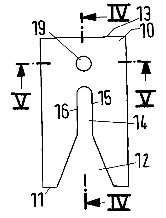
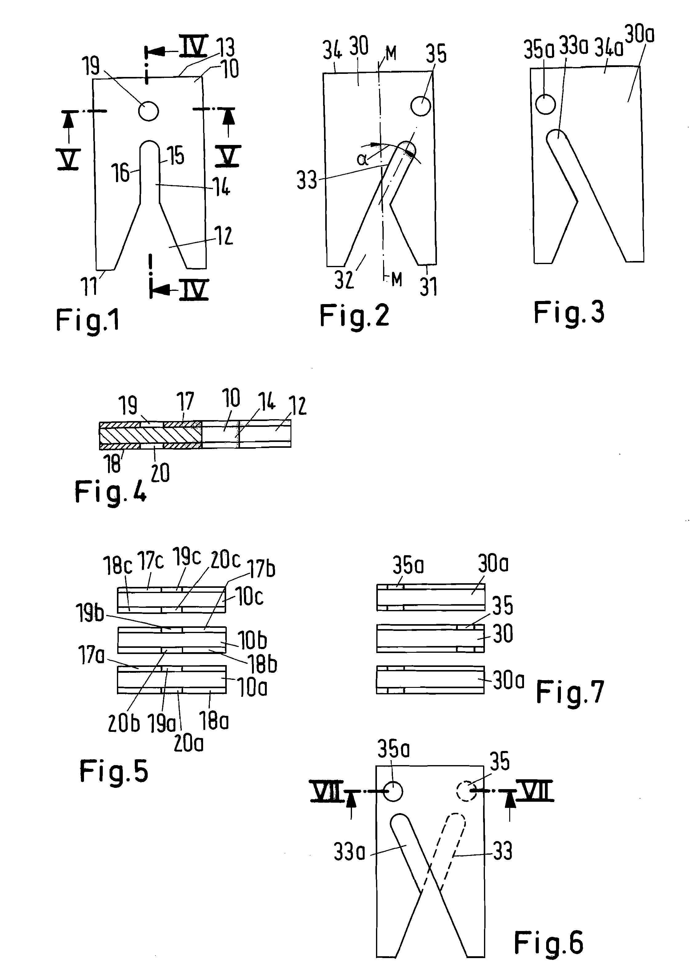
[0011]An aspect of the present invention is to provide an arc splitter arrangement which leads to an improvement in quenching and switching characteristics in comparison to the known arrangements, wherein restrikes and flashovers outside the splitter stack are prevented by the arc being stabilized at the burning point. A flashover between the plates is avoided, and local melting of individual plates is prevented.
[0013]Thus, according to the present invention, an area in the form of an island or a zone like an island is left uncoated on each plate, into which uncoated zone the arc is deliberately guided and is preferably intended to burn in the area of the uncoated zone. In this case, it could oscillate in the uncoated area, and local melting can be prevented by the oscillation.
[0017]According to a further refinement of the invention, the insulating coating may have characteristics which emit gas or vapour under the influence of an arc; this promotes current limiting.

Problems solved by technology

One problem in the movement of the arc or of the individual arc elements within the arc splitter stack is that, without further measures, the arc can flash over or restrike at the end of the arc splitter stack or else on the side edges, thus preventing current limiting and correct short-circuit disconnection.
However, since the material is consumed, the number of switching operations which can be carried out is limited.

Method used


Image

  • Arc splitter arrangement for an electrical switch
  • Arc splitter arrangement for an electrical switch

Examples


Embodiment Construction

[0025]An electrical circuit breaker, which will not be described in any more detail here, but whose construction is known per se, has a contact point with a stationary contact piece and a moving contact piece which is fitted on a contact lever, each of which have associated arc guide rails which run parallel and hold between them an arc splitter stack as shown in FIGS. 1 to 7. The fact that a circuit breaker such as this has a latching mechanism, a switching toggle, a thermal and electromagnetic release as well as connecting terminals, a switching toggle and a capability for mounting on a top-hat profile mounting rail will not be described in any more detail here.

[0026]When a short-circuit current occurs, for example, when a switching operation takes place, that is to say the opening of the contact point, the arc foot point of an arc which burns between the stationary contact piece and the moving contact piece is created on the stationary contact piece and on the moving contact piec...


PUM


Abstract

An arc splitter arrangement for an electrical switch comprises at least two arc splitters composed of a ferromagnetic material disposed parallel to one another, wherein each of the at least two arc splitters has a V-shaped cutout on a narrow face edge forming an inlet area for an arc, and an insulating material at least partially coating at least one side of the arc splitter, wherein the at least one side includes an area located behind the inlet area in an arc running direction, the area being free of, and surrounded by, the insulating material. A service switching device comprises at least one arc splitter arrangement.

Description

[0001]Priority is claimed to German Patent Application No. DE 10 2008 017 868.3, filed on Apr. 9, 2008, the entire disclosure of which is incorporated by reference herein.[0002]The invention relates to an arc splitter arrangement for a service switching device, in particular for a circuit breaker, a motor circuit breaker or a contactor, having arc splitters which are arranged parallel to one another.[0003]The invention furthermore relates to a service switching device having an arc splitter stack such as this.BACKGROUND[0004]An arc splitter arrangement of this generic type, also referred to as an arc splitter stack or else a deionizing splitter stack, is used in particular in a circuit breaker, a motor circuit breaker or in a contactor, with the aim of disconnecting not only rated currents but also overcurrents and in particular short-circuit currents. It operates in such a way that an arc which is created at a contact point when it opens is introduced as a result of the current for...

Claims


Application Information

Patent Timeline
Patent Type & Authority Applications(United States)
IPC IPC(8): H01H9/44
CPCH01H73/18H01H9/36
Inventor ANDRE, GERALDBAHLINGER, THILO
Owner ABB (SCHWEIZ) AG
Why Eureka
Eureka Blog
Learn More