Electrostatic dust collector

A technology of electrostatic precipitator and dust collection plate, which is applied in the field of electrostatic precipitator, can solve the problems of weak heat resistance, affecting service life, and affecting dust removal efficiency, etc., and achieves the effect of facilitating neutralization and condensation

Active Publication Date: 2013-01-30
易敏红
View PDF6 Cites 9 Cited by
  • Summary
  • Abstract
  • Description
  • Claims
  • Application Information

AI Technical Summary

Problems solved by technology

Therefore, for high specific resistance dust, tempering and spray treatment are required, and the operating efficiency is still not ideal
[0005] 2. It is not easy to purify low specific resistance dust
The above process occurs repeatedly, which affects the dust removal efficiency
[0006] Although the dust collection poles of ordinary dust collectors adopt various forms with grooves to prevent secondary dust, the blocking effect is still not ideal. The electric wind formed by the drive will turn back after reaching the dust collecting pole to form many eddies. These vortices will disturb the settlement order of the dust particles reaching the dust collecting pole, so that some dust particles will float back to the flue and be carried by the flue gas flow. go, thereby reducing the dust removal efficiency
[0007] 3. High steel consumption of equipment
Ordinary electrostatic precipitators usually use thorn-type cathode discharge electrodes, and anodes use sedimentation plates, so the consumption of metal plates is large and the equipment cost is high
[0008] 4. Large waste of running power
However, the lightweight dust-collecting plate composed of light-weight insulating damping strips is easily disturbed by electric field flow, and has weak thermal resistance, so it can only be used in low-temperature environments; the additional electric field composed of lightweight dust-collecting plates and insulating pole lines is In the static dust collection area generated by its flat plate structure, the dust can still escape; the insulated pole line in the original additional electric field is easily damaged by strong corrosive smoke and dust, which affects the service life

Method used


Image

  • Electrostatic dust collector
  • Electrostatic dust collector
  • Electrostatic dust collector

Examples


Embodiment 1

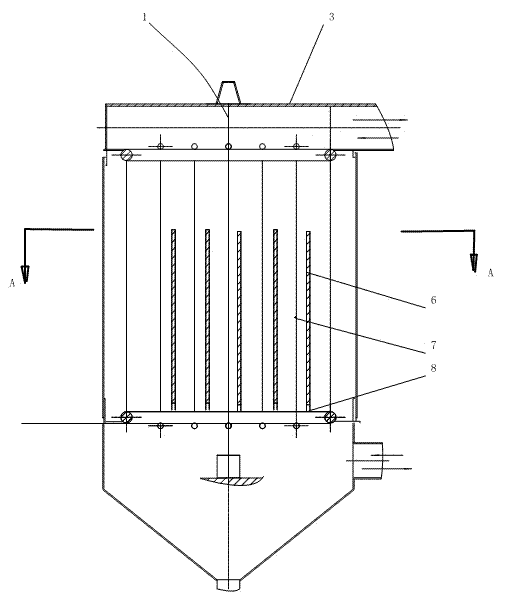
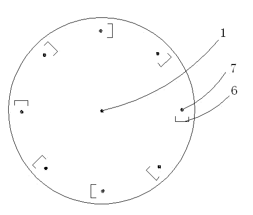
[0039] The electrostatic precipitator of the present embodiment is a cylindrical precipitator, such as figure 1 As shown, it includes a casing 3 , which is cylindrical, and the casing 3 is provided with a cathode 1 , an anode 7 and a dust collecting plate 6 close to the anode 7 . The cathode 1 and the anode 7 of the present embodiment adopt metal wires, the cross section of the dust collection plate 6 is groove-shaped and half surrounds the anode 7, the distance range between the dust collection plate 6 and the anode 7 is 10mm, and the upper and lower sides of the dust collection plate 6 The ends are respectively fixed on the upper and lower ends of the housing 1 through insulators 8.

[0040] In this embodiment, the insulator 8 and the insulator 8 are as Figure 5 and Figure 6 As shown, the material of the insulator 8 is ceramic, mica or tetrafluoroethylene, and the whole is umbrella-shaped. The middle section of the insulator 8 is provided with tooth-shaped protrusions. ...

Embodiment 2

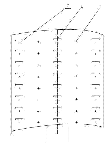
[0045] The electrostatic precipitator of this embodiment is a box-type precipitator, and the difference from Embodiment 1 is that the housing is in the shape of a cuboid box, and the anodes and cathodes are alternately arranged at intervals of a set distance. Fabric in multiple rows.

[0046] (1) if image 3 and Figure 4 As shown, the housing 3 of this embodiment is in the shape of a cuboid box, and the anodes 7 and cathodes 6 are alternately arranged in multiple rows at intervals of 500 mm. The dust collecting plate 6 of this embodiment adopts a groove-shaped plastic plate, and the distance between the dust collecting plate 6 and the anode 7 is 80mm.

[0047] (2) The cathode 1 and anode 7 of this embodiment use conductive plastic wires.

[0048] (3) In this embodiment, the insulator 8 is in the shape of a dumbbell, with through holes at both ends, as shown in the figure. The insulators 8 are respectively connected with the dust collecting plate 6 and the housing 1 with p...

Embodiment 3

[0050] This embodiment is an improvement on the basis of Embodiment 2, and the difference from Embodiment 2 is:

[0051] (1) The dust collecting plate 6 is made of arc-shaped metal plate, and the distance between the dust collecting plate 6 and the anode 7 is 150mm; in this embodiment, the dust collecting plate 6 is made of a metal plate to improve the resistance to heat change.

[0052] (2) if Figure 9 As shown, the cathode 1 is provided with buckles 1-2 at intervals along the length direction, and each buckle 1-2 is provided with at least one metal wire 1-1. In this embodiment, the cathode 1 adopts such a structure, which can effectively strengthen the corona discharge.

[0053] (3) The cathode 1 and the anode 7 of this embodiment use conductive rubber wires.


PUM


Abstract

The invention relates to an electrostatic dust collector, belonging to the technical field of electrostatic dust collection. The dust collector comprises a housing, a cathode and an anode made of electric conductive wires are arranged in the housing, and a dust collection board which is parallel with the anode and whose length is basically equal to that of the anode is arranged close to the anode; the dust collection board semi-surrounds the anode from one side of the anode, the scope of the distance between the dust collection board and the anode is 5-150mm, and the upper end and the lower end of the dust collection board are respectively and fixedly arranged on the upper end and the lower end of the housing through an insulator; and the overall insulator is of an umbrella shape or a dumbbell shape. According to the electrostatic dust collector, the dust collection efficiency is high, various specific resistance dusts can be collected, and any modulation is not needed.

Description

technical field [0001] The invention relates to an electrostatic precipitator, which belongs to the technical field of electrostatic precipitator. Background technique [0002] More than 100 years have passed since the first electrostatic precipitator was born in 1906. Its main part of the electric field structure has not undergone major changes. It is still the discharge of corona wires and the collection of dust by the dust collector, while the problems of back corona and dust re-flying have always been No good solution was found. [0003] For the working principle and structure of the electrostatic precipitator commonly used at present, see pages 25-113 of "Electrostatic Precipitator" edited by Li Zaishi (Metallurgical Industry Press, first edition in 1997). This kind of electrostatic precipitator adopts the principle of cathode discharge and anode dust collection, and has the following disadvantages: [0004] 1. It is not easy to collect high specific resistance dust. ...

Claims


Application Information

Patent Timeline
Patent Type & Authority Applications(China)
IPC IPC(8): B03C3/04B03C3/40
Inventor 易敏红
Owner 易敏红
Why Eureka
Try Eureka