Ink-ribbon transfer device capable of fixing rotary roller

A transmission device, a technology of fixing the rotating shaft, applied in the direction of inking device, ink ribbon cassette, printing, etc.

Inactive Publication Date: 2007-02-14
HI TOUCH IMAGING TECH CO LTD
View PDF0 Cites 1 Cited by
  • Summary
  • Abstract
  • Description
  • Claims
  • Application Information

AI Technical Summary

Problems solved by technology

[0008] Therefore, the present invention provides a color ribbon transmission device with a fixed shaft to solve the

Method used


Image

  • Ink-ribbon transfer device capable of fixing rotary roller
  • Ink-ribbon transfer device capable of fixing rotary roller
  • Ink-ribbon transfer device capable of fixing rotary roller

Examples


Embodiment Construction

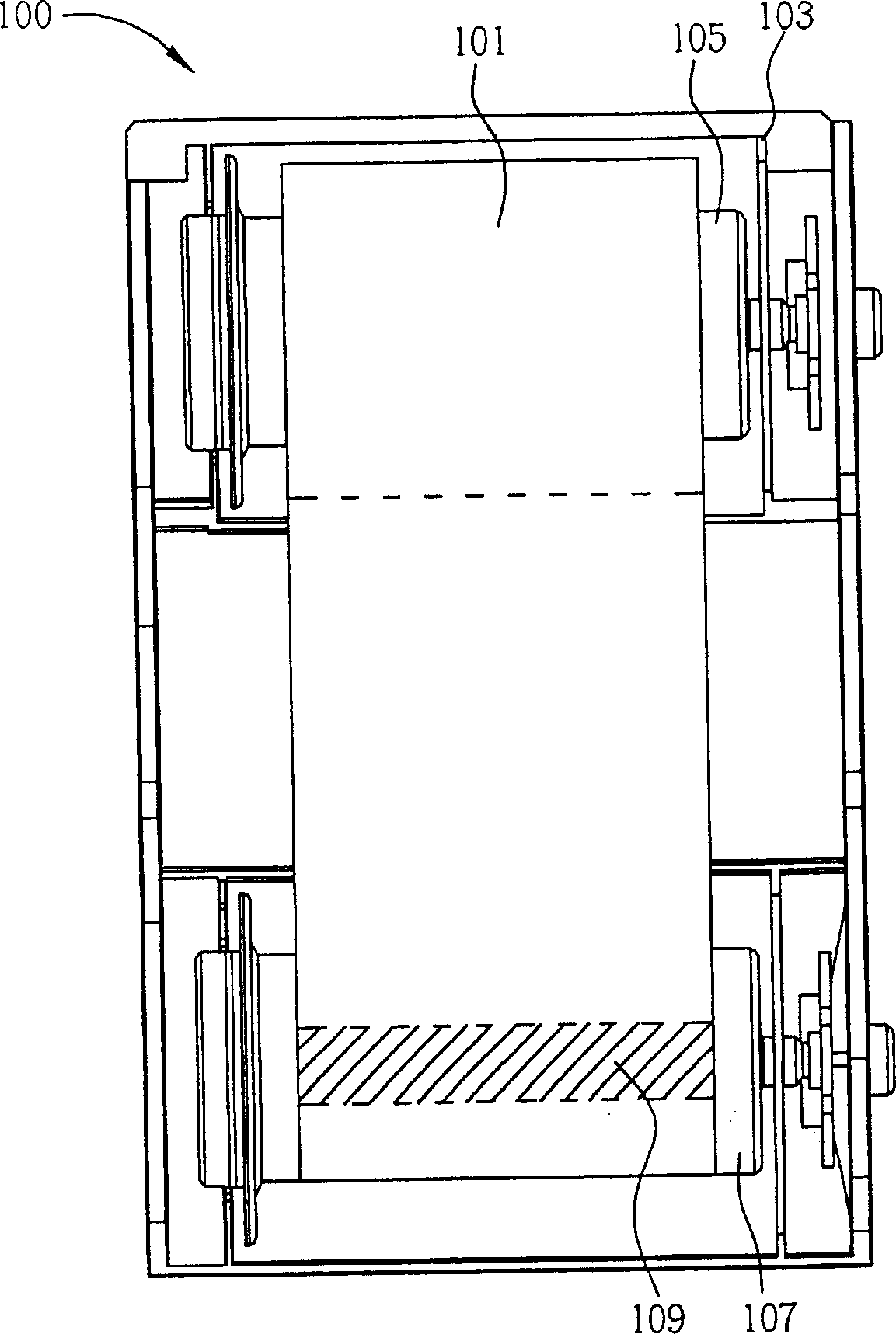
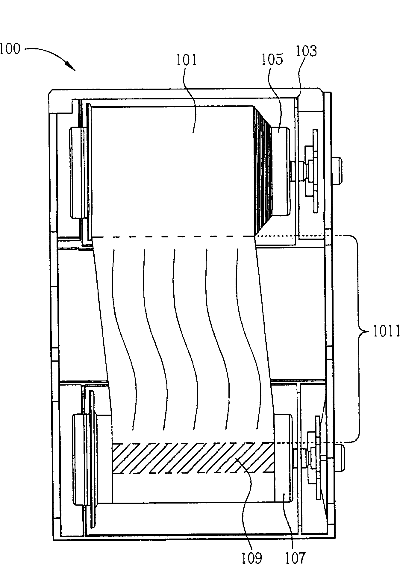
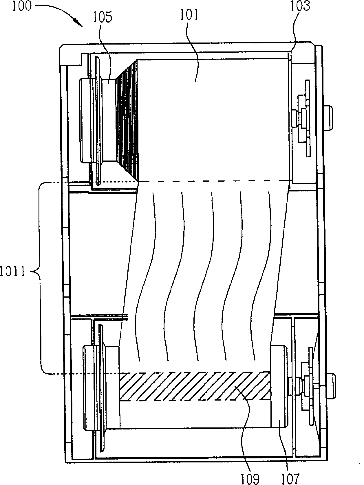
[0017] Figure 5 A partial perspective view of two fixing parts 213 and 215 is configured for the ribbon conveying device 200 of the present invention, wherein a ribbon 201 is wound on the first rotating shaft 205 of the ribbon conveying device 200 . The ribbon transmission device 200 of the present invention includes a ribbon cassette 203, a first rotating shaft 205, and a second rotating shaft 207 ( Figure 5 not shown), a detachable first fixing part 213, and a detachable second fixing part 215. Please note that in order to clearly illustrate the positions where the two fixing members 213 and 215 are installed on the ribbon conveying device 200, Figure 5 Only a part of the color belt transmission device 200 is shown, and the two fixing parts 213 and 215 are as Figure 5 As shown, it is mounted on the ribbon conveying device 200 in a penetrating manner. The detailed structure of ribbon transfer device 200 of the present invention will be Figure 6 are detailed in the fr...


PUM


Abstract

The present invention is one ink ribbon conveyer with one fixed rotation shaft, and the ink ribbon conveyer includes one ink ribbon cassette, two rotation shafts and two fixtures. These two fixtures are mounted on two sides of one rotation shaft and penetrated through the rotation shaft and the ink ribbon cassette so as to fix the rotation shaft and the ink ribbon cassette relatively. Owing to the fixtures, the ink ribbon conveyer of the present invention can avoid the rotation of the shaft caused by external forces during transportation and prevent the loosening of the ink ribbon wound onto the shaft and the exposure of the ink ribbon cassette.

Description

technical field [0001] The invention relates to a color ribbon transmission device, in particular to a color ribbon transmission device capable of fixing a rotating shaft. Background technique [0002] For the existing ribbon transmission device, since the shaft used to drive the ribbon is not properly fixed during the transportation process, the shaft is easily affected by external forces, such as vibration during transportation or other unpredictable vibration, while rotating relative to the ribbon cassette. In this way, the rotating shaft can easily drive the ribbon wound on it, so that part of the ribbon can be unfolded, and even the ribbon can be loosened and exposed outside the ribbon box. In addition, the existing ribbon conveying device is prone to skew due to similar reasons, even if the position of the ribbon on the rotating shaft deviates from the preset position. When printing the ribbon, the rotating shaft will drive the ribbon to move from the supply end of t...

Claims


Application Information

Patent Timeline
IPC IPC(8): B41J32/00
Inventor 林岳正
Owner HI TOUCH IMAGING TECH CO LTD
Why Eureka
Try Eureka