
Light conducting device, manufacturing and operating method

A technology of a light guide device and a manufacturing method, which is applied in the direction of optical waveguide light guide, light guide, optics, etc., and can solve the problems that it is not easy to reduce the size of the light guide device, etc.

Inactive Publication Date: 2005-01-26
AU OPTRONICS CORP
View PDF0 Cites 0 Cited by
  • Summary
  • Abstract
  • Description
  • Claims
  • Application Information

AI Technical Summary

Problems solved by technology

Also, it is not easy to downsize the light guide due to its material properties

Method used


Image

  • Light conducting device, manufacturing and operating method
  • Light conducting device, manufacturing and operating method
  • Light conducting device, manufacturing and operating method

Examples


Embodiment Construction

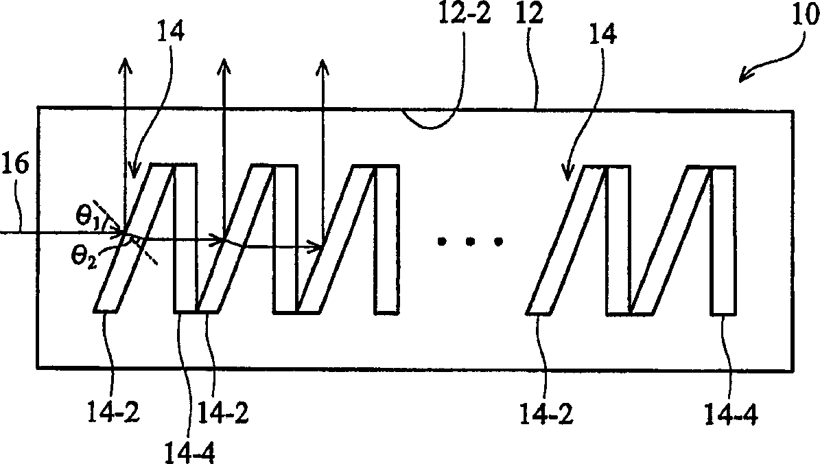
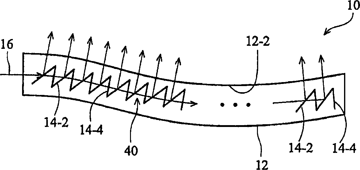
[0040] figure 1 It is a schematic diagram of a light guide device 10 according to an embodiment of the present invention. The light guide 10 includes a first thin film 12 having a first index of refraction and a second thin film 14 having a second index of refraction different from the first index of refraction. The first film 12 and the second film 14 are transparent optical films. According to an embodiment of the present invention, the materials of the first film 12 and the second film 14 are transparent optical glue. In another embodiment, the first membrane 12 and the second membrane 14 are flexible. The first film 12 includes a surface 12-2 serving as a light emitting surface and an accommodating portion disposed therein. The second film 14 is disposed on the first film 12 in a wave form, and includes a plurality of mutually parallel first segments 14-2 and a plurality of mutually parallel second segments 14-4. These first segments 14- 2 and the second segment 14 - 4...


PUM


Abstract

A light guide device having light propagating therein that comprises a first film of a first index of refraction including a surface, a second film of a second index of refraction different from the first index of refraction formed in the first film in a waveform, a plurality of first parts of the second film formed parallel to each other, and a plurality of second parts of the second film corresponding to the first parts formed parallel to each other, wherein a part of the light is reflected toward the surface of the first film when the propagating light is incident upon one of the first parts of the second film.

Description

technical field [0001] The present invention relates to a light guide device, and in particular to a flexible light guide device for a liquid crystal display. Background technique [0002] A light guide assembly for a liquid crystal display usually includes a light source and a wedge-shaped light guide device. The light guide device can convert the light supplied by the light source from a linear mode to a planar mode. In general, the known light guides are made of acrylic or plastic materials, which are not flexible so as not to distort the optical path determined by their structure. Furthermore, due to its material properties, it is not easy to downsize the light guide. [0003] Therefore, there is a need for a light guide device and a manufacturing method thereof to overcome the above-mentioned shortcomings of the prior art. Therefore, a special flexible light guide plate is required to solve the problem of optical distortion in the prior art SUMMARY OF THE INVENTION...

Claims


Application Information

Patent Timeline
Patent Type & Authority Applications(China)
IPC IPC(8): G02B6/00F21V8/00G02B6/10G02F1/1335G02F1/13357
CPCG02B6/0033G02B6/0028
Inventor 孙明申
Owner AU OPTRONICS CORP
Learn More