Wire rod feeding device

A technology for conveying devices and wire rods, applied in the direction of operating devices, forging/pressing/hammer devices, metal processing equipment, etc., can solve the problems of small force, inconvenience, small contact area, etc., and achieve the effect of fast and stable transportation

Active Publication Date: 2007-02-28
台湾铧司企业股份有限公司
View PDF0 Cites 7 Cited by
  • Summary
  • Abstract
  • Description
  • Claims
  • Application Information

AI Technical Summary

Problems solved by technology

However, because the clamping surface 211 is ring-shaped, and only a partial area of ​​the opposite side abuts against the surface of the wire 10, and the contact area between the roller 21 and the wire 10 is too small, the relative force of the clamping surface 211 t

Method used


Image

  • Wire rod feeding device
  • Wire rod feeding device
  • Wire rod feeding device

Examples


Embodiment Construction

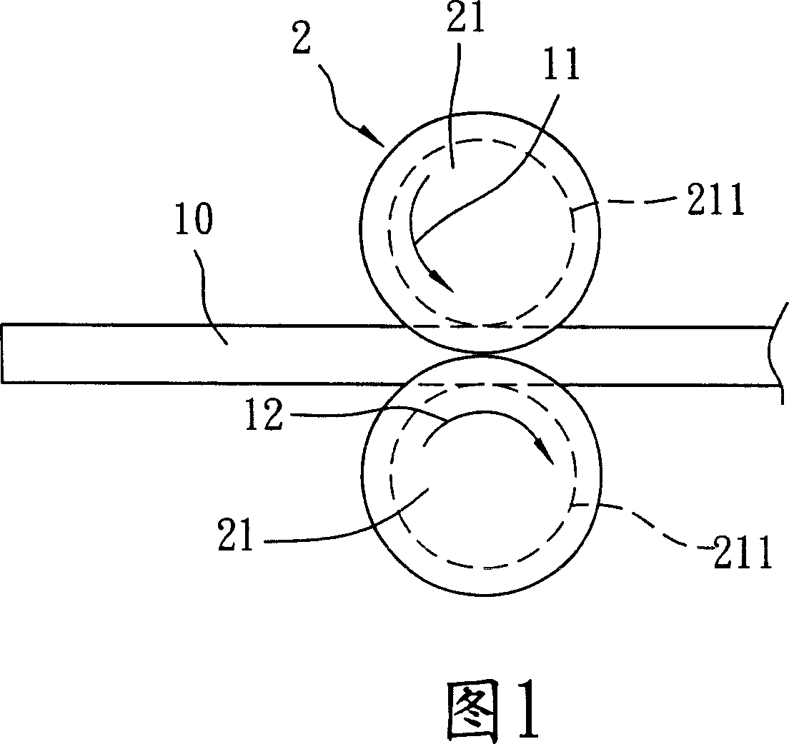
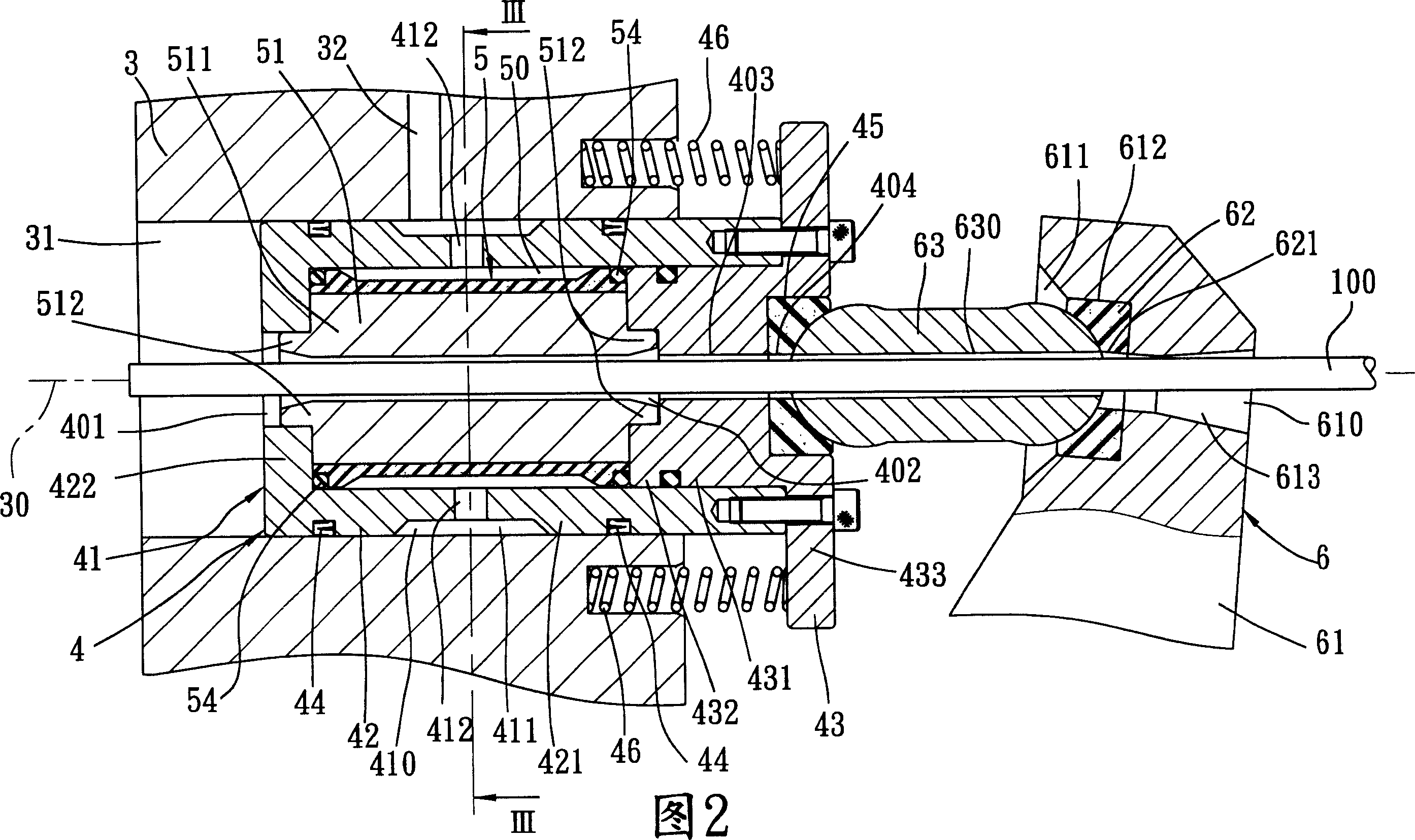
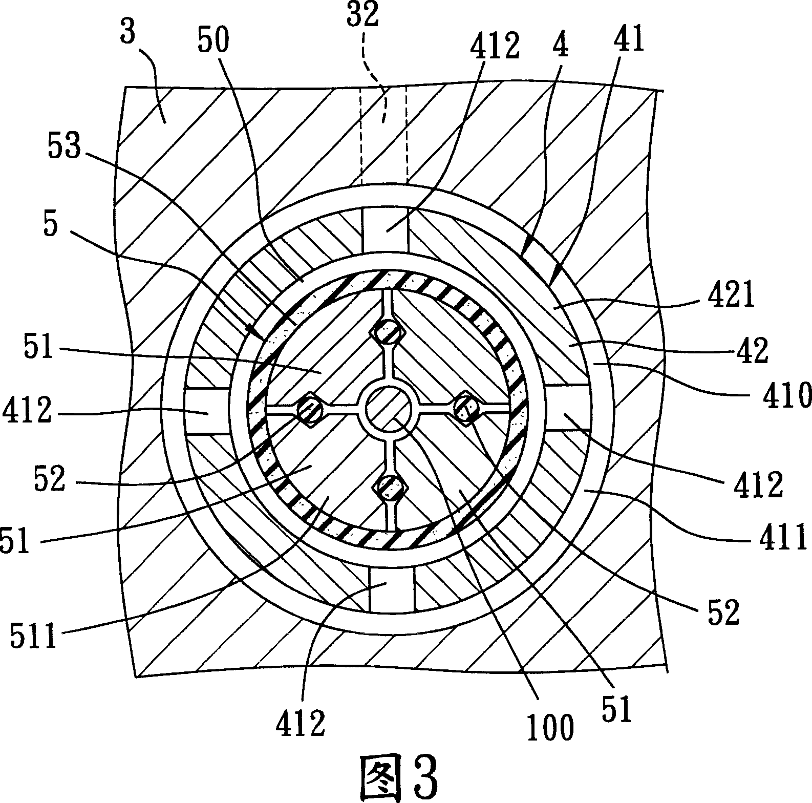
[0013] As shown in Figures 2 and 3, the embodiment of the wire conveying device of the present invention can be used to convey a long wire 100, including a base 3, a wire clip assembly unit 4 assembled on the base 3 and a wire clip Unit 5, and a pushing unit 6 assembled on the right side of base 3 and combined with clamp assembly unit 4.

[0014] The base 3 has an assembly hole 31 extending left and right along an axis 30 , and a flow guide hole 32 extending up and down and communicating with the assembly hole 31 through its bottom end for injecting high-pressure fluid (not shown). In this embodiment, the high-pressure fluid may be liquid or gas.

[0015] The clamp assembly unit 4 includes a moving mechanism 41 airtightly inserted in the assembly hole 31 and having a dispensing hole 410 communicated with the flow guide hole 32, and two upper and lower parts assembled on the right side of the base 3 at intervals. and the elastic reset member 46 between the moving mechanism 41 ...


PUM


Abstract

The invention discloses a wire transmitting device, which comprises the following parts: base, wire assembling unit, wire unit and pushing unit, wherein the wire assembling unit contains a mobile mechanism in the assembling hole on the base, which concludes at least two groups of wire block in the mobile mechanism and elastic cylinder oil seal on two separation wire blocks, the pushing unit anchors mobile mechanism to move reciprocally, which makes wire transmit stably and rapidly to provide a stable force for locating the wire.

Description

【Technical field】 [0001] The invention relates to a conveying device, in particular to a wire conveying device. 【Background technique】 [0002] As shown in Figure 1, it is a common wire conveying device 2 in a general forging parts forming machine. Ring-shaped clamping surface 211, when the conveying device 2 transports a wire 10, the wire 10 passes through the gap on the opposite side of the clamping surface 211 of the roller 21, and is clamped between the clamping surfaces 211, and is separated by the roller 21. The wire 10 is continuously pinched forward by rotating in the directions shown by arrows 11 and 12 . However, because the clamping surface 211 is ring-shaped, and only a partial area of ​​the opposite side abuts against the surface of the wire 10, and the contact area between the roller 21 and the wire 10 is too small, the relative force of the clamping surface 211 to clamp the wire 10 is relatively small. The strength is very small, and most of them can only be...

Claims


Application Information

Patent Timeline
IPC IPC(8): B21K27/02
Inventor 李文元
Owner 台湾铧司企业股份有限公司
Why Eureka
Try Eureka