
An environmentally friendly efficient desulfuration dust collector

A desulfurization dust collector and dust collector technology, applied in chemical instruments and methods, dispersed particle filtration, use of liquid separators, etc., can solve the problem of incomplete dust removal in the dust collector, and achieve enhanced spray desulfurization effect, good effect and resistance. small effect

Inactive Publication Date: 2018-12-14
河南东贵电子科技有限公司
View PDF6 Cites 0 Cited by
  • Summary
  • Abstract
  • Description
  • Claims
  • Application Information

AI Technical Summary

Problems solved by technology

[0004] The object of the present invention is to provide an environmentally friendly and efficient desulfurization dust collector for the above-mentioned problem of incomplete dust removal by the existing dust collector

Method used


Image

  • An environmentally friendly efficient desulfuration dust collector
  • An environmentally friendly efficient desulfuration dust collector

Examples


Embodiment 1

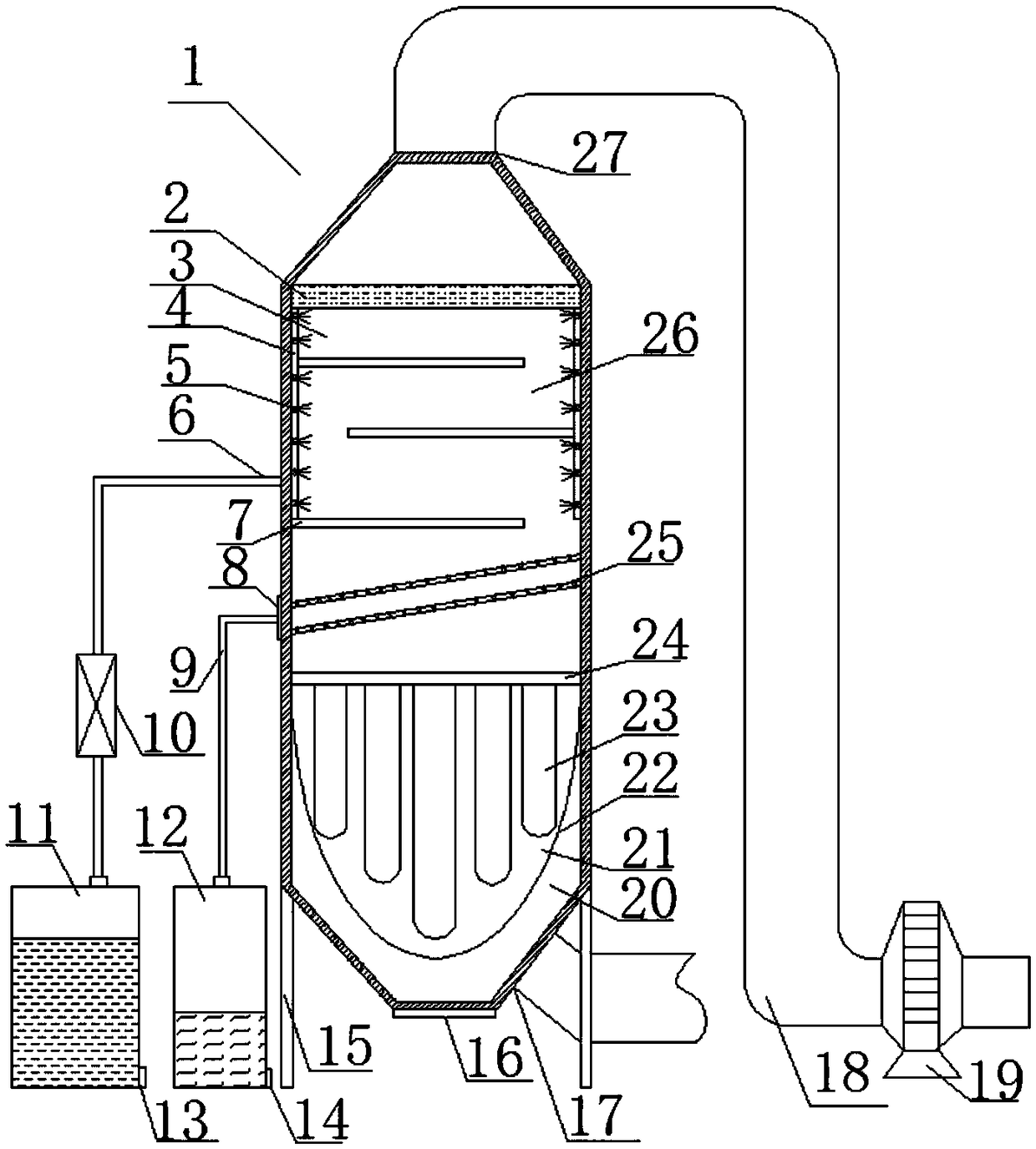
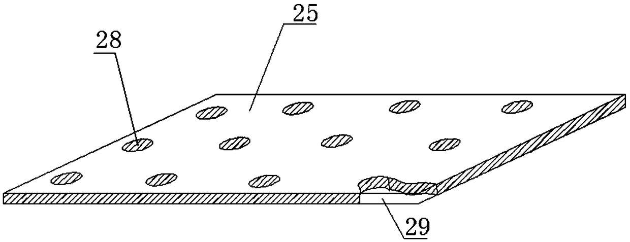
[0030] Such as figure 1 As shown, an environmentally friendly and efficient desulfurization dust collector includes a dust collector body 1 and a support frame 15, and is characterized in that: the bottom of the dust collector body 1 is provided with an air inlet 17 and a dust outlet 16, and the top is provided with an air outlet 27, The air outlet 27 is connected to the fan 19 through the gas pipeline 18, and the dust collector body 1 includes a bag dust removal chamber 20, a spray chamber 3 and a packing layer 2 from bottom to top, and the bag dust removal chamber 20 and the spray chamber 3 are separated by inclined air-permeable plates 25, and the bag filter 21 is fixedly installed on the inner wall of the bag dust removal chamber 20, and several spray pipes 4 are fixedly installed on the inner walls of the spray chamber 3, and Several nozzles 5 are arranged on the spray pipes 4 .

[0031] The working principle and process of this technical solution are as follows:

[003...

Embodiment 2

[0035] According to Example 1, such as figure 1 As shown, the cloth bag filter 21 includes a large cloth bag 22 and a cloth bag bracket 24 fixedly connected to the inner wall of the bag dust removal chamber 20. Several small cloth bags 23 are also arranged in the large cloth bag 22, and the large cloth bag 22 and the small cloth bag The cloth bags 23 are all combined and fixed by the cloth bag bracket 24. The cloth bag filter 21 is provided with two layers of cloth bags, large and small, which can effectively enhance the filtering effect.

Embodiment 3

[0037] According to Example 1, such as figure 1 As shown, any two pairs of sides of the inner wall of the spray chamber 3 are fixedly connected with a plurality of partitions 7 that divide the spray chamber 3 into S-shaped gas passages 26 . The S-shaped gas channel 26 separating the spray chamber 3 can prolong the path and time for the gas to pass through the spray chamber 3, effectively enhancing the desulfurization effect of the spray.


PUM


Abstract

The invention relates to an environmentally friendly efficient desulfuration dust collector. The desulfuration dust collector includes a dust collector main body and a support. The bottom of the dustcollector main body is provided with a gas inlet and a dust outlet, and the top of the main body is provided with a gas outlet connected to a draught fan through a gas pipeline. The main body includesa bag type dust collection chamber, a spraying chamber and a filler layer in order from bottom to top. Inclined permeable plates are disposed between the bag type dust collection chamber and the spraying chamber. A bag filter fixedly mounted to the inner wall of the bag type dust collection chamber is disposed in the bag type dust collection chamber. A plurality of spraying pipes are fixedly mounted to the periphery inner wall of the spraying chamber and are provided with a plurality of spray nozzles. The bag type dust collection chamber, the spraying chamber and the filler layer are disposedin the main body in order so that dry type dust collection and wet dust collection are combined, dust and harmful and toxic substances such as sulfur dioxide in gas can be removed at the same time, and dust is thoroughly removed with good effects.

Description

technical field [0001] The invention relates to the technical field of environmental protection, in particular to an environmentally friendly and efficient desulfurization and dust collector. Background technique [0002] Dust collector is a device that separates dust from flue gas, called dust collector or dust removal equipment. [0003] At present, the dust collectors used more in industrial flue gas dedusting include dry dust collectors and wet dust collectors. Although the dry dust collectors have better dust removal effects, they cannot remove harmful sulfur dioxide and other harmful substances in the flue gas due to functional limitations. In the wet dust collector, there are components that can form a water film inside, so that the sulfur dioxide in the flue gas can be absorbed by the water film and taken away with the water flow to remove it. The effect is somewhat unsatisfactory. The existing dust collector cannot combine the functions of the dry dust collector a...

Claims


Application Information

Patent Timeline
Patent Type & Authority Applications(China)
IPC IPC(8): B01D50/00B01D46/02B01D47/06B01D53/04B01D53/50B01D53/78
CPCB01D46/023B01D47/06B01D53/0407B01D53/50B01D53/78B01D2258/0283B01D2253/34B01D50/60
Inventor 王超
Owner 河南东贵电子科技有限公司
Learn More