Horizontal centrifugal mist eliminator

A mist eliminator and horizontal technology, which is applied in the field of exhaust gas purification and treatment, can solve the problems of lack of mist removal effect and the like

Inactive Publication Date: 2012-10-17
张宏生
View PDF5 Cites 4 Cited by
  • Summary
  • Abstract
  • Description
  • Claims
  • Application Information

AI Technical Summary

Problems solved by technology

The disadvantage of this device is that there will still be a small amount of water mist discharged from the center of the spiral water tank, and the defogging effect is still lacking.

Method used


Image

  • Horizontal centrifugal mist eliminator
  • Horizontal centrifugal mist eliminator
  • Horizontal centrifugal mist eliminator

Examples


Embodiment Construction

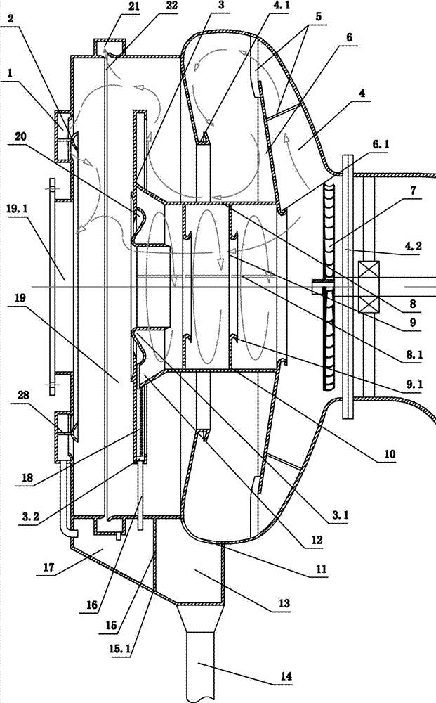
[0021] Such as figure 1 As shown, the present invention is a horizontal centrifugal mist eliminator for removing water mist in the airflow. The exhaust tank 19 of water tank 4 and rear side. The front side of the water ski tank 4 is provided with an air inlet 4.2, and at the air inlet 4.2 of the water ski tank 4, a rerouting fan blade 7 driven by a motor is installed. After the airflow mixed with water mist passes through the rerouting fan blade 7, Because the water itself has gravity, most of the water mist is thrown around by the diversion fan blade 7, and a small amount of water mist is discharged forward with the air-flow. An air exhaust port 19.1 is provided at the center of the rear end surface of the air exhaust tank 19, and the pure air after demisting by the cylinder is discharged from the air exhaust port 19.1.

[0022] The side wall of the water ski tank 4 diverges in an arc from front to back, the rear side of the water ski tank 4 is recessed inward, and an e...


PUM


Abstract

A horizontal centrifugal mist eliminator comprises a cylinder body connected with an inlet pipe at the front. The cylinder body comprises water slide tank at the front and an exhaust air tank at the rear; a side wall of the water slide tank radiates outward from front to back arcuately; the back side of the water slide tank concaves inward; and an air exhaust ring is arranged at the center of the back side of the water slide tank. The water slide tank is provided with a guide plate; a friction distribution tank is mounted on the back of the guide plate; the rear end of the friction distribution tank passes through the air exhaust ring on the water slide tank; and a plurality of annular friction damping plates are arranged on the inner wall of the friction distribution tank. The mist eliminator of the invention is mainly combined with the atomization dedusting device; tail gas fully contacts with water mist by the atomization dedusting device, so that smoke and toxic substances in tail gas are mixed with water; then smoke and toxic substance mist is condensed into water through the water slide tank, the friction distribution tank and a steam separating tank; and eventually air flow in the water mist is separated out. The invention has the advantages of simple structure and complete demisting.

Description

technical field [0001] The invention belongs to the field of tail gas purification treatment, and specifically refers to a device for separating the mist from the airflow mixed with water mist in an atomization dust removal device, so that the discharged airflow does not contain water mist. Background technique [0002] With the development of industry, the discharge of various industrial waste gases is increasing day by day. Industrial waste gases often contain smoke and a large amount of toxic substances, which will not only pollute the environment, but also seriously affect the health of workers and residents around the factory. The existing exhaust gas treatment device mainly sprays water mist on the exhaust gas, so that the smoke and toxic substances in the exhaust gas are mixed into the water mist, and clean gas is discharged. However, if the water mist is not separated, the water mist mixed with soot and toxic substances carried by the discharged airflow will still po...

Claims


Application Information

Patent Timeline
Patent Type & Authority Applications(China)
IPC IPC(8): B01D45/14
Inventor 张宏生
Owner 张宏生
Why Eureka
Try Eureka