Electronic lock controlled cabinet

A technology for electronic locks and cabinets, which is applied in cabinets, chests of drawers, building locks, etc. It can solve the problems of tools and documents being accessed or read by non-specific personnel, loss of control tools and documents, and inconvenient use.

Inactive Publication Date: 2007-03-14
张 庭维
View PDF0 Cites 7 Cited by
  • Summary
  • Abstract
  • Description
  • Claims
  • Application Information

AI Technical Summary

Problems solved by technology

[0003] The above-mentioned locking device locks the drawer in a mechanical way. Therefore, a key is required to open or lock the drawer in use. When opening each drawer, it must be done by the person who keeps the key. The operation of opening is quite inconvenient to use, and after a long time of use, the key is often copied widely, causing the tools and documents placed in the drawer to be accessed or read by non-specific personnel, making the locking device Loss of functionality of control tools and documents

Method used


Image

  • Electronic lock controlled cabinet
  • Electronic lock controlled cabinet
  • Electronic lock controlled cabinet

Examples


Embodiment Construction

[0025] Please refer to FIG. 1 to FIG. 7 , which show the structure of the selected embodiment of the present invention.

[0026] The electronic lock control cabinet of this embodiment includes:

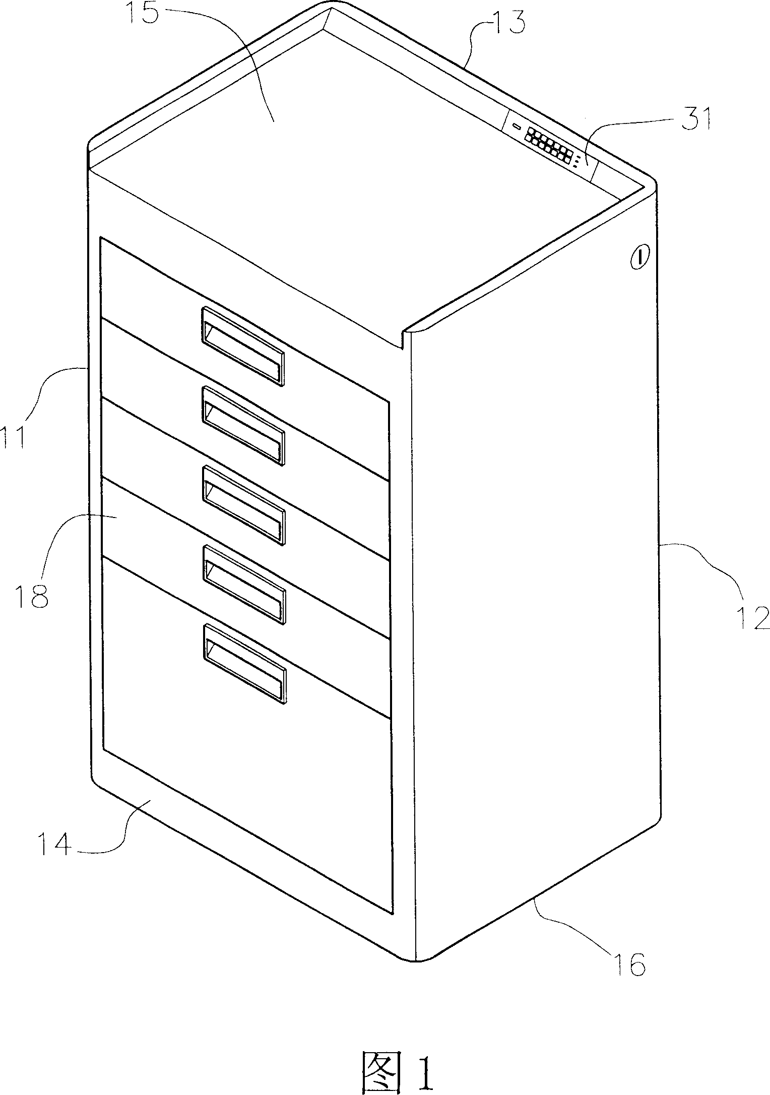
[0027] A box body 1, which includes being surrounded by five panels to have an inner space and a flat plate 14 facing the user and having an opening, each panel is a top panel 15, a bottom panel 16, and a first parallel to each other A panel 11 and a second panel 12 are matched with a third panel 13 that is also parallel to the flat panel 14, and several slide grooves 17 are provided on the first and second panels 11 and 12 for several bottoms. The drawer 18 of a hook part 181 is slidably set;

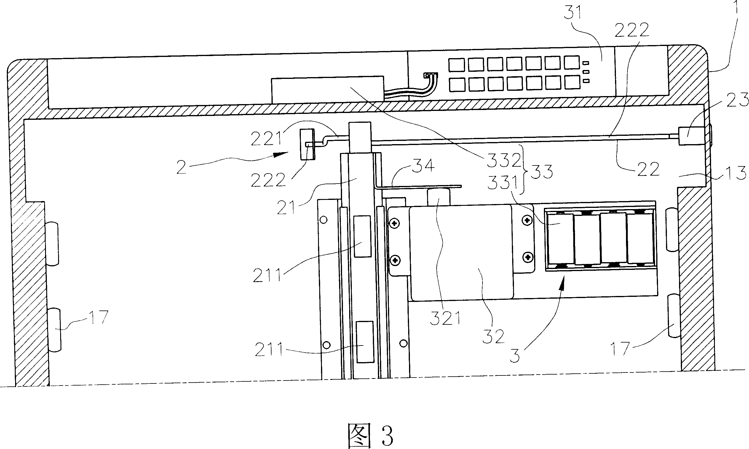
[0028] A locking mechanism 2 has a vertical slide rail 21 that can move up and down. The vertical slide rail 21 is located on the inner side of the third panel 13 and has several locking holes 211 for the hook parts of each drawer 18. 181 is fixed, and a working hole 212 is set on the side n...


PUM


Abstract

A cabinet controlled by electro-lock, including: a box, an internal space around by 5 panels. And there is a plate with openings moving towards users for several drawer the bottom of which with clips could move front and back; a lock-immovable mean with a lengthways slide track up and down, the lengthways slide track is located in the box and has several lock hole, for the clips of the drawer fixing, there is a work hole near the side near the top of the lengthways slide track for a rotating horizontal-axis rod thrills through; an electronic body with a control panel is connected with a locked controller and a power supply unit by dint of a circuit, the locked controller is connected with the lengthways slide track by a interlock component, to start locked controller by the control panel sequentially drive the interlock component and last make the lengthways slide track move up and down. The invention is based on password settings and setup time to on or off to control the lock-immovable mean to achieve precise control effectiveness.

Description

technical field [0001] The invention relates to an electronic lock control cabinet body. Background technique [0002] Generally, the existing cabinet has a box body, and several drawers that can slide freely are arranged in the box body for placing tools or documents. The body is provided with a locking device for locking the drawer, so that the drawer of the cabinet body can be locked firmly without loosening when not in use, so as to achieve the effect of protecting personal privacy. [0003] The above-mentioned locking device locks the drawer in a mechanical way, so a key is required to open or lock the drawer in use. When opening each drawer, it must be done by the person who keeps the key. The operation of opening is quite inconvenient to use, and because the key is often copied widely after long-term use, the tools and documents placed in the drawer are often accessed or read by non-specific personnel, making the locking device Loss of functionality of control tools...

Claims


Application Information

Patent Timeline
IPC IPC(8): A47B67/04E05B65/46E05B65/462
Inventor 张庭维
Owner 张 庭维
Why Eureka
Try Eureka