Valve for essentially gastight closing a flow path

A flow path and airtight technology, applied in the direction of sliding valves, lift valves, valve details, etc., can solve the problems that aluminum is not suitable for corrugated parts, etc., and achieve the effects of reduced danger, small flow loss, and small reaction surface

Inactive Publication Date: 2007-03-14
VAT HLDG AG
View PDF1 Cites 19 Cited by
  • Summary
  • Abstract
  • Description
  • Claims
  • Application Information

AI Technical Summary

Problems solved by technology

However, aluminum is hardly suitable for the production of bellows which can be stretched considerably
[0007] Another disadvantage is that the above-mentioned structure of the valve mechanism makes the valve have a relatively elongated structure

Method used


Image

  • Valve for essentially gastight closing a flow path
  • Valve for essentially gastight closing a flow path
  • Valve for essentially gastight closing a flow path

Examples


Embodiment Construction

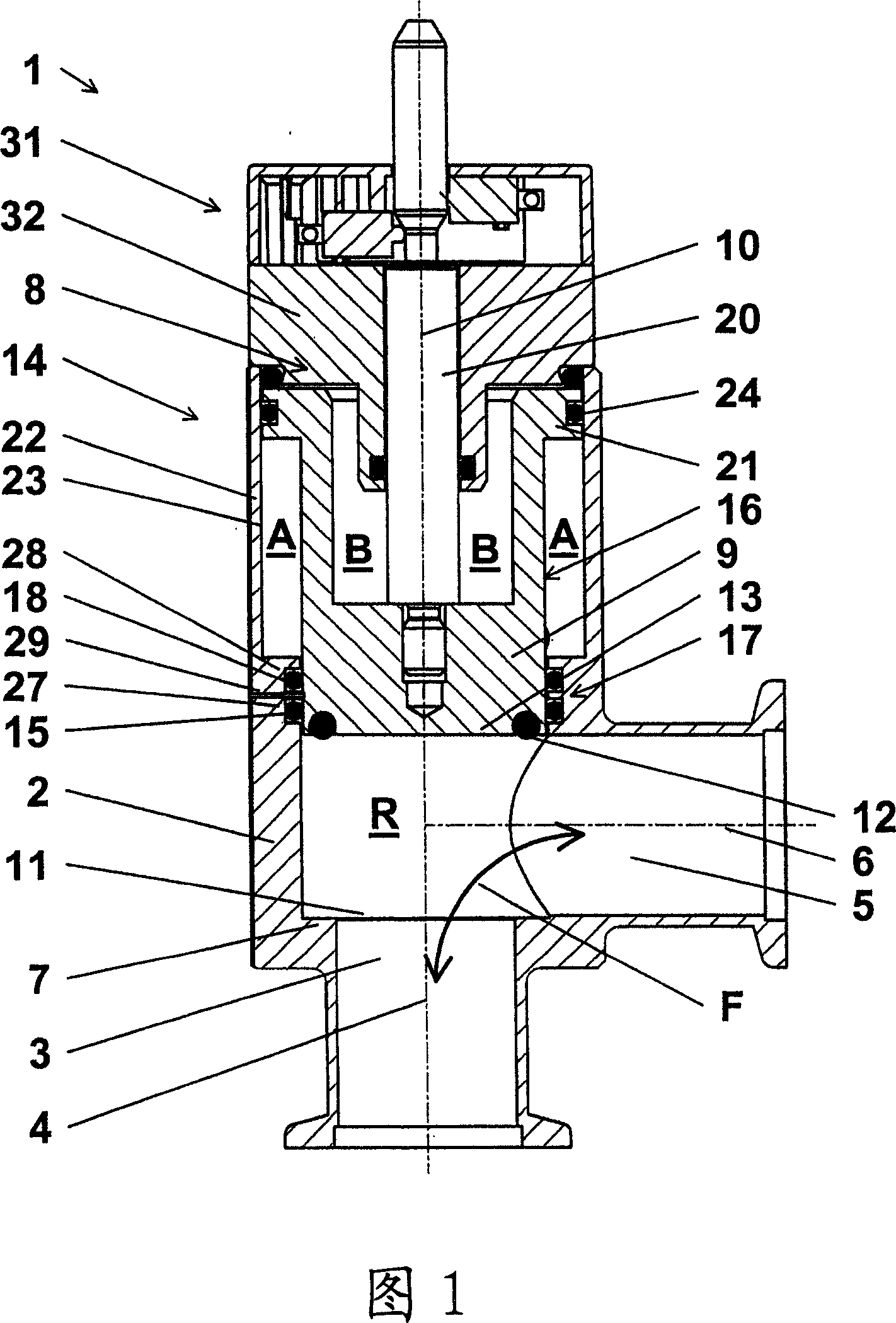
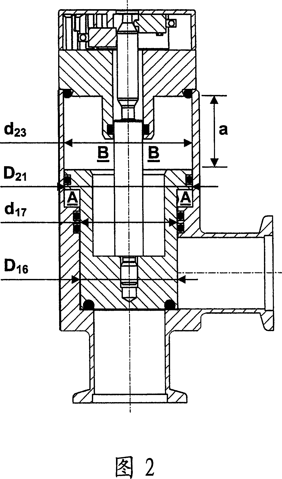
[0026]FIG. 1 shows an embodiment of a valve 1 according to the invention in a longitudinal section in a fully open state. The same valve 1 is shown in Figure 2, but in a fully closed state. Therefore, Figs. 1 and 2 will be described together below. In FIG. 2 , reference numbers already shown in FIG. 1 are omitted.

[0027] The valve 1 has a valve housing 2 comprising a first port 3 and a second port 5 . Both port 3 and port 5 have a circular section and are in the form of a connection to the flow space R of valve 1 . The ports 3 and 5 are arranged perpendicular to each other (in an angled form) such that the first axis 4 of the first port 3 is perpendicular to the second axis 6 of the second port 5 . The first axis 4 and the second axis 6 are defined by the longitudinal axes of the ports 3 and 5 . The flow passage F in the flow space R interconnects the first port 3 and the second port 5 in the open state of the valve 1 . Formed in the valve housing 2 is a valve seat 7 wh...


PUM


Abstract

Maintenance-friendly, compact valve having a simple design for essentially gastight closing of a flow path between two ports arranged at an angle. A valve part which is arranged in a valve housing so as to be displaceable along an axis and whose closing surface can be brought into contact with a valve seat of the first port for closing the flow path and can be brought out of contact for opening the flow path is in the form of a cylindrical piston having an end face forming the closing surface and a piston outer surface. The valve housing has a cylindrical passage which extends opposite the valve seat along the axis and through which the piston is passed and can be displaced and inside which a sealing or guide element is arranged. The piston and the passage are dimensioned so that the piston outer surface is closely enclosed along the adjustment distance by the sealing or guide element of the passage. It is thus possible for essentially only a single adjustable component of the valve, namely the easily cleanable piston consisting in particular of a single material, to be guided in the flow space so that the maintenance of the valve is substantially simplified and few different materials bound the flow space. In a further development, the drive mechanism of the piston is formed at least partly by an outer piston space between a piston step and the passage, so that the piston forms a component of the drive mechanism, permitting a compact design of the valve.

Description

technical field [0001] The present invention relates to a valve for substantially gas-tight closing of a flow passage between two ports disposed at an angle. In particular, the invention relates to a valve comprising a valve member, the closure surface of which is contactable with a valve seat of a first port to close said flow passage and disengageable to open said flow passage. Such valves are used in particular in vacuum technology and are specifically known as vacuum angle valves. Background technique [0002] Valves of the type mentioned at the outset are known in various embodiments from the prior art. Vacuum valves are used in particular in the field of IC and semiconductor production, which must be carried out in a protected atmosphere which is as free as possible of contaminating particles. [0003] The valves disclosed in the prior art and described in, for example, US Pat. In the flow space in the flow path connecting the two ports. In the bonnet closing this ...

Claims


Application Information

Patent Timeline
Patent Type & Authority Applications(China)
IPC IPC(8): F16K1/00F16K31/122
CPCF16K51/02F16K27/02F16K31/56F16K3/22F16K3/24
Inventor 格布哈特·卢茨
Owner VAT HLDG AG
Why Eureka
Try Eureka