Supercharge Your Innovation With Domain-Expert AI Agents!

Optical information device, and information recording/reproducing device

A technology for information recording and optical information, which is applied to optical recording/reproducing, optical recording heads, beam guiding devices, etc. Effect

Inactive Publication Date: 2007-04-04
PANASONIC CORP
View PDF1 Cites 2 Cited by
  • Summary
  • Abstract
  • Description
  • Claims
  • Application Information

AI Technical Summary

Problems solved by technology

In this way, when the fluctuation amount ΔPP of the signal amplitude greatly fluctuates, the gain of the tracking control decreases at the tracks Tn-1 and Tn, the tracking control becomes unstable, and there is a problem that it is impossible to record and reproduce signals with high reliability.

Method used


Image

  • Optical information device, and information recording/reproducing device
  • Optical information device, and information recording/reproducing device
  • Optical information device, and information recording/reproducing device

Examples


no. 1 Embodiment approach

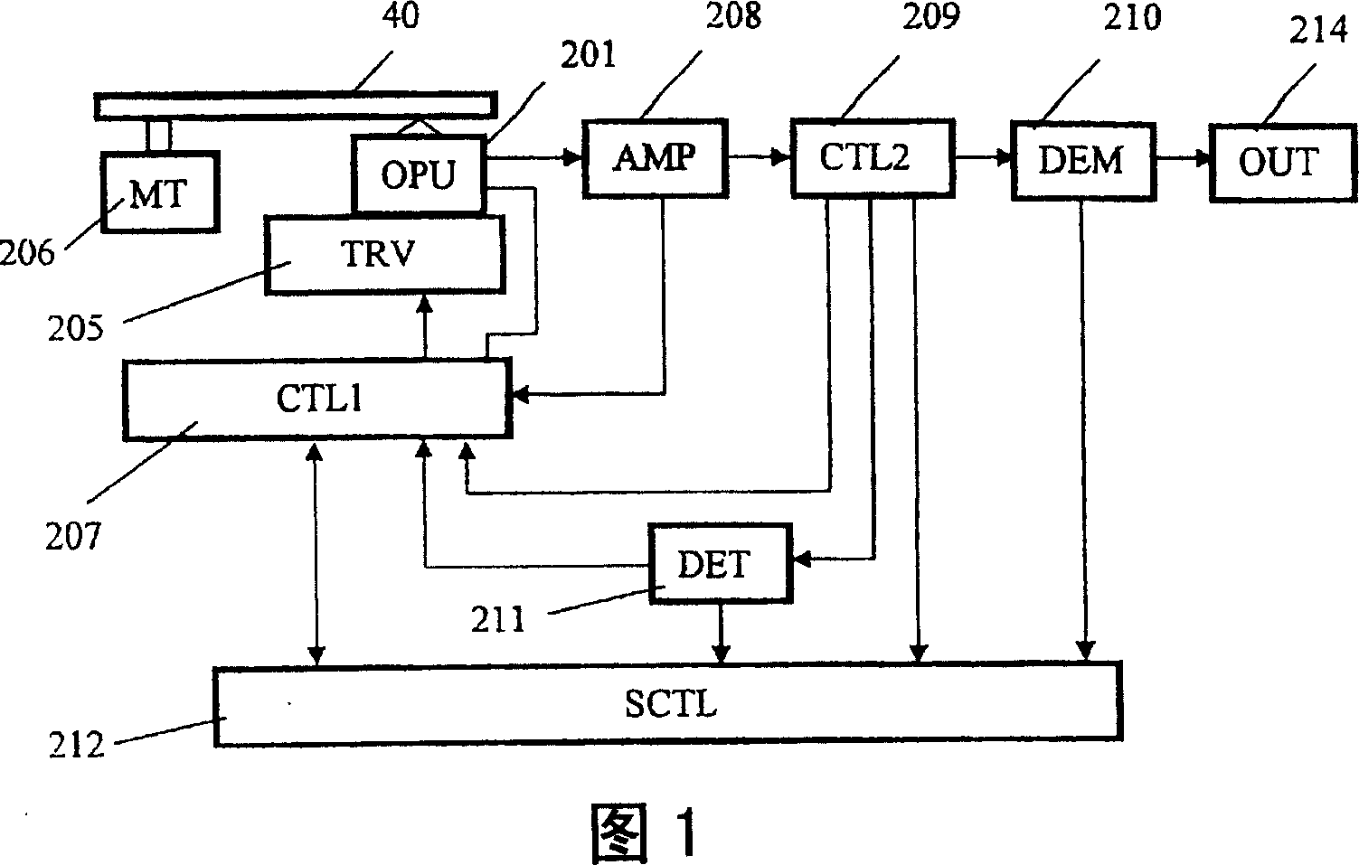
[0054] FIG. 1 shows the configuration of an optical information device according to this embodiment.

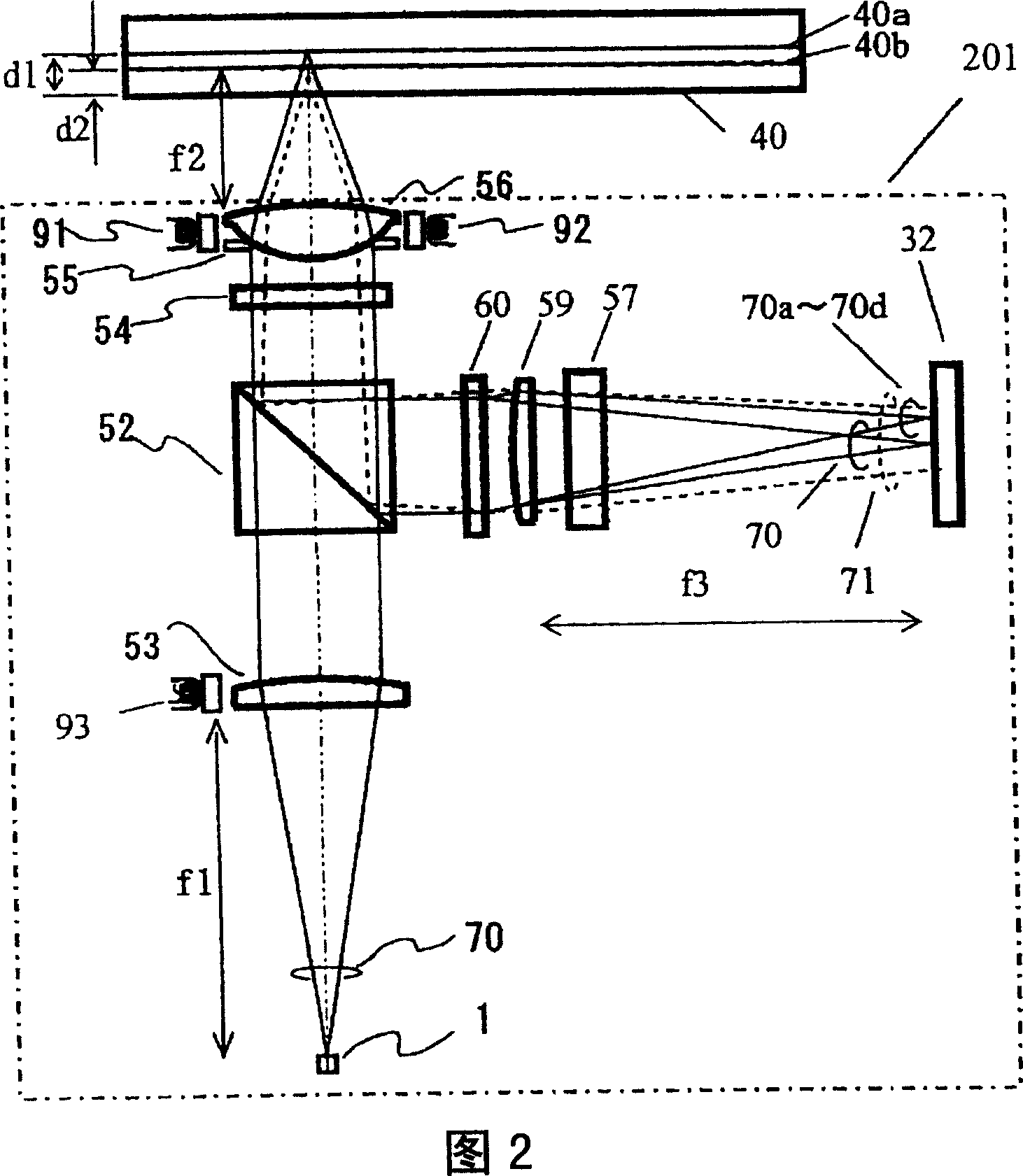
[0055] The optical pickup device 201 (or also called "optical pickup") irradiates the optical recording medium 40 with laser light having a wavelength λ of 405 nm, and reproduces the signal recorded on the optical recording medium 40 . The transport controller 205 moves the optical pickup device 201 along the radial direction of the optical recording medium 40 in order to record or reproduce information at an arbitrary position on the optical recording medium 40 . The motor 206 of the optical recording medium 40 is driven to rotate the optical recording medium 40 . The controller 207 controls the optical pickup device 201 , the transfer controller 205 and the motor 206 .

[0056] The amplifier 208 amplifies the signal read by the optical sensor head device 201 . The controller 209 receives the output signal from the amplifier 208 . Based on the signal, the controller 209 g...

no. 2 Embodiment approach

[0068] FIG. 8 is a diagram schematically showing the photodetector 33 used in this embodiment and the relationship between the light beam 70, the light beam 71, and the light beams 70a to 70d received by the photodetector 33, respectively.

[0069] The optical pickup of this embodiment differs from the optical pickup of the first embodiment in that a photodetector 33 is used instead of the photodetector 32 . The difference between the photodetector 32 and the photodetector 33 is that, with respect to the center of the light beam 71 reflected from the information recording surface 40b that is not in focus, the photodetectors are arranged at positions approximately symmetrical to the axis of the photodetectors 33e to 33h. 33i~33l. When K is a real number, the TE signal when using such a photodetector 33 can be given by (I33e-I33j)-(I33f-I33i)-K·(I33h-I33k)-(I33g-I33l).

[0070]At this time, the stray light of the light beam 71 incident on the information recording surface 40b o...

no. 3 Embodiment approach

[0072] FIG. 9 is a diagram schematically showing the photodetector 34 used in this embodiment and the relationship between the light beam 70 received by the photodetector 34 and the light beams 70a to 70n, respectively.

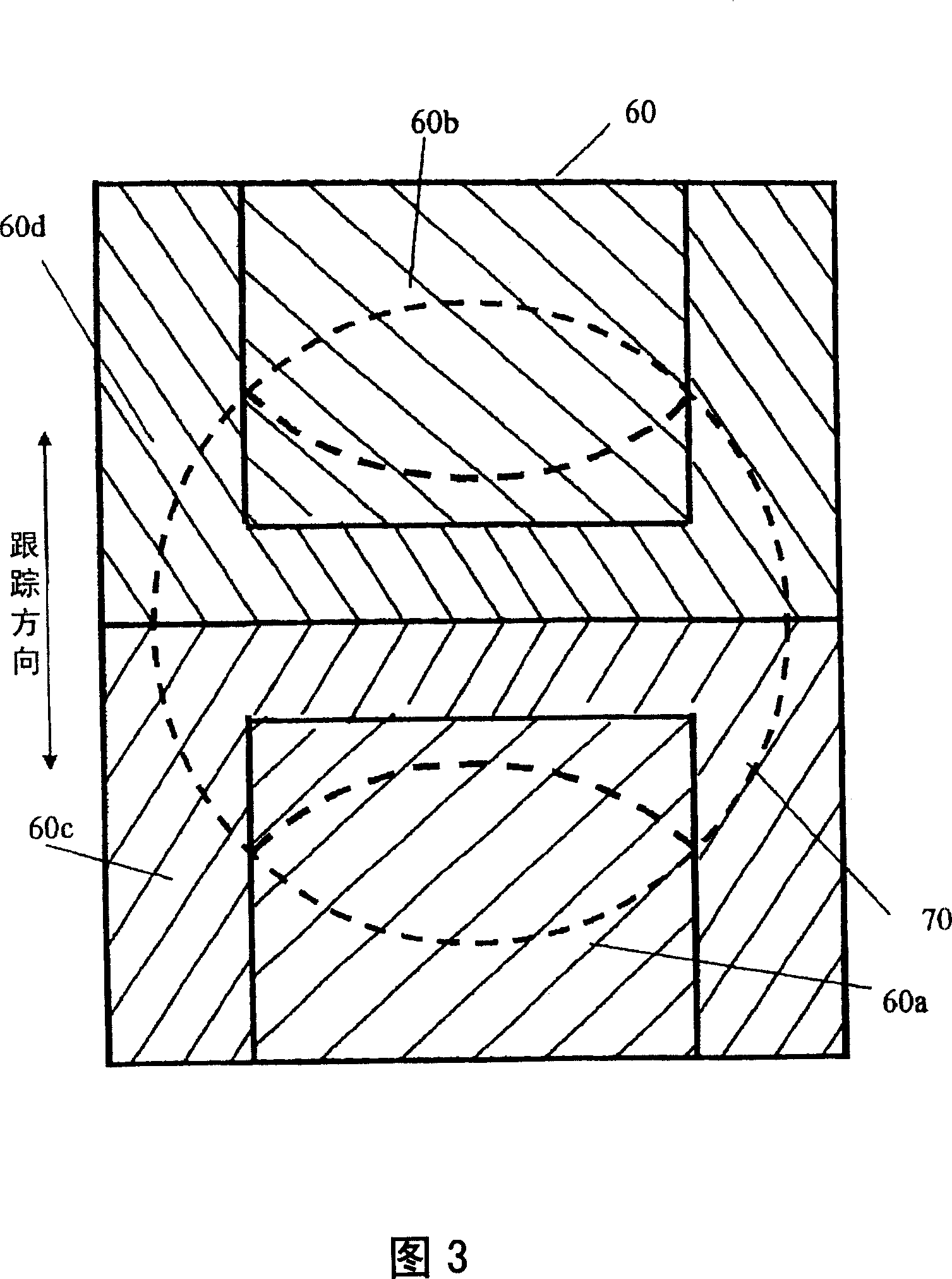
[0073] The difference between the optical pickup of this embodiment and the optical pickup of the first embodiment is that instead of the diffraction grating 60, an unillustrated diffraction grating 61 is used; device 34. In the first embodiment, the groove cross-sectional shape of the diffraction grating 60 may be any of a simple groove shape or a stepped or zigzag grating shape. However, the diffraction grating 61 of this embodiment has a simple groove shape that generates ± diffracted light. In addition, like the diffraction grating 60 of FIG. 3 , it has four types of regions 61a to 61d.

[0074] Next, the beam split by the diffraction grating 61 will be described. The +1st-order diffracted light reflected by the information recording surface 40b and di...


PUM

PropertyMeasurementUnit
thicknessaaaaaaaaaa
thicknessaaaaaaaaaa
refractive indexaaaaaaaaaa

Abstract

An optical information device includes a light source for emitting an optical beam, converging means for collecting the optical beam emitted from the light source onto a predetermined information recording surface of the optical recording medium having a plurality of information recording surfaces, beam division means for dividing the optical beam reflected by the optical recording medium, and photo-detection means having a light reception unit for receiving the optical beam divided by the beam division means and outputting a signal in accordance with the light intensity of the optical beam received by the light reception unit. A guide groove is formed on at least one of the information recording surfaces. The light reception unit is arranged entirely in a map formed on the photo-detection means by the optical beam reflected from the information recording surface other than the predetermined information recording surface (hereinafter, referred to as non-light-collecting surface). It is possible to realize stable tracking control for an optical recording medium having a plurality of information recording surfaces.

Description

technical field [0001] The present invention relates to an optical information device and an information recording / reproducing device, in particular to an optical information device for recording, reproducing or erasing information on an optical recording medium, and using the optical information device to record, reproduce or erase information on an optical recording medium optical information recording / reproducing device. Background technique [0002] As a high-density and large-capacity recording medium, a high-density and large-capacity optical disk called DVD has been put into practical use for several years, and it is widely used as an information medium for processing a large amount of information such as moving images. [0003] FIG. 13 shows the structure of an optical pickup used for recording and reproducing such an optical recording medium in the prior art. Here, the optical recording medium is irradiated with three light beams, and a tracking error signal is det...

Claims


Application Information

Patent Timeline
Patent Type & Authority Applications(China)
IPC IPC(8): G11B7/09G11B7/135G11B7/13
CPCG11B7/0901G11B7/1381G11B2007/0013G11B7/0909G11B7/131G11B7/1353
Inventor 安西穰儿门胁慎一山崎文朝森荣信
Owner PANASONIC CORP
Features
  • R&D
  • Intellectual Property
  • Life Sciences
  • Materials
  • Tech Scout
  • Unparalleled Data Quality
  • Higher Quality Content
  • 60% Fewer Hallucinations
Learn More