Mop

A mop and shell technology, applied in the field of mops, can solve the problems of weak installation force of the mop, easy to fall off, inconvenient to replace the dirty mop, etc.

Inactive Publication Date: 2007-04-18
SAMJUNG CLEAN MASTER
View PDF0 Cites 7 Cited by
  • Summary
  • Abstract
  • Description
  • Claims
  • Application Information

AI Technical Summary

Problems solved by technology

[0004] However, the above-mentioned existing mop is not only easy to fall off during use due to the weak installation force of the mop, but also very inconvenient to replace the dirty mop after use.

Method used


Image

  • Mop
  • Mop
  • Mop

Examples


Embodiment Construction

[0019] Embodiments of the present invention will be further described below in conjunction with the accompanying drawings.

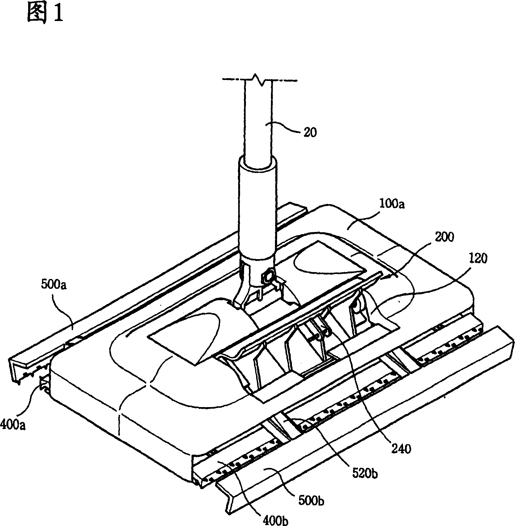
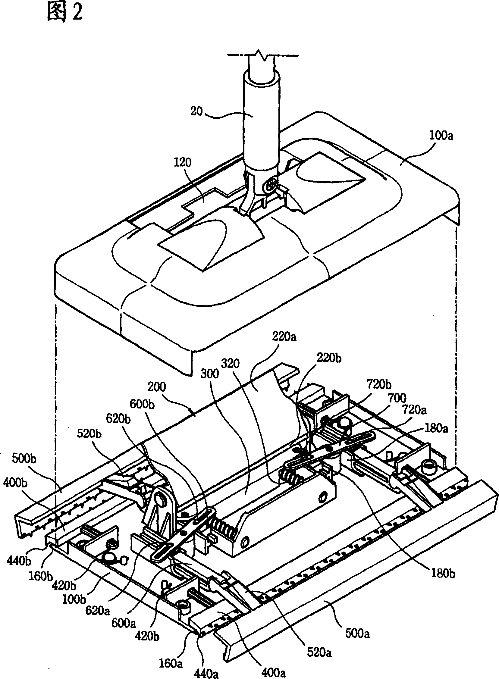
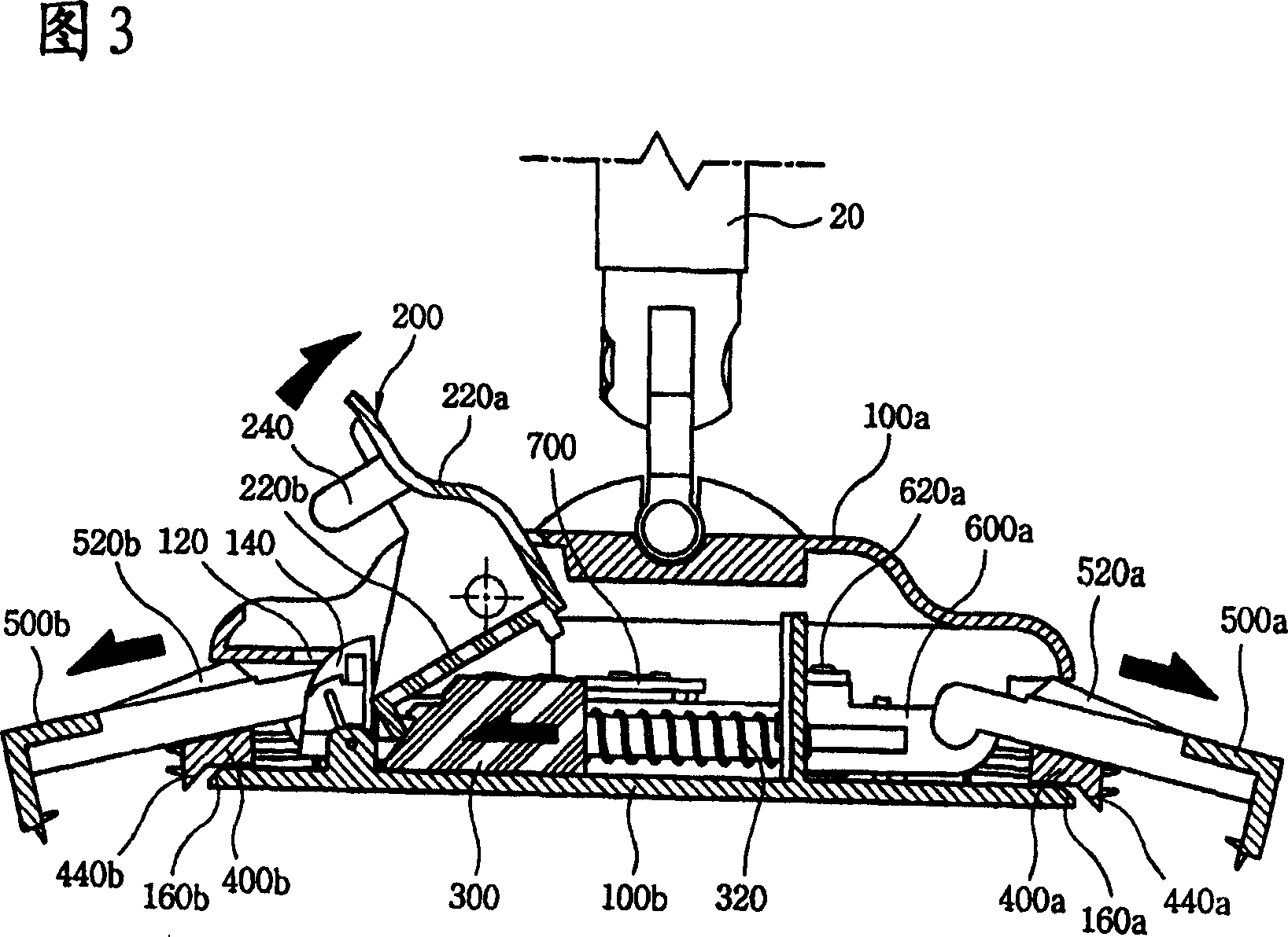
[0020] Fig. 1 is a perspective view of the mop of the present invention, Fig. 2 is an exploded perspective view of the mop of the present invention, Fig. 3 is a side sectional view of the mop of the present invention when it is opened, and Fig. 4 is a side view of the mop of the present invention when it is closed Sectional view, Fig. 5 is a bottom view of the mop of the present invention when it is opened, Fig. 6 is a bottom view of the mop of the present invention when it is closed, and Fig. 7 is a partial sectional view of the mop of the present invention.

[0021] As shown in Figures 1 to 7, the mop of the present invention mainly includes: a main body housing 100a, 100b divided into upper / lower sides, a rotating plate 200 that is pressed by the user and moved according to the action of the rotating plate. Slider 300 that slides forward / backward, fro...


PUM


Abstract

Provided is a mop with the profile shape, wherein the cloth is arranged on the subface of the main body, cleaning with the mop rod at the middle part of the case, characterized by including: a host case with an open end formed on the case and the upper and lower case yoking with one another; a rotor plate shaft coupling at the open end of the host case and realizing the locking or cancelling the action through pushing the button; a slider moving forward and backward through the rotation of the rotor plate and the coil shape spring supported by the host case; an inside / outside lock located in the front / back of the host case for grasping the front / back end of the mop through separating or clinging each other; a pair of front / back push rod combined with the front / back outside lock mounted on the slider side of the host case at an intervals; and a rotation link rod making a pair of the front / back push rod act simultaneously combining with the front / back push rod at a definite distance.

Description

technical field [0001] The present invention relates to a kind of mop which is equipped with a mop on the lower casing of the main body and combined with a mop rod in the middle of the upper casing to clean the floor. A mop that can easily attach and detach the mop attached to the lower case. Background technique [0002] Generally speaking, the mop is equipped with a mop on the lower shell of its main body, and wipes the floor by a rotating mop rod connected to the upper shell. [0003] Above-mentioned mop is improved into various forms, and one of them example is exactly that main body is made into plate shape, and mop is loaded onto in its lower shell, and the mop that rotatably connects mop rod is connected in upper shell. [0004] However, the above-mentioned existing mop is not only easy to fall off during use due to the weak installation force of the mop, but also very inconvenient to replace the dirty mop after use. Contents of the invention [0005] In order to ...

Claims


Application Information

Patent Timeline
Patent Type & Authority Applications(China)
IPC IPC(8): A47L13/24
CPCA47L13/258A47L13/44
Inventor 沈禹锡
Owner SAMJUNG CLEAN MASTER
Why Eureka
Try Eureka