Yarn feeder

A kind of equipment and yarn feeding technology, which is applied in the direction of thin material processing, textile and paper making, loom, etc., can solve the problems that the joint area is easy to be damaged, and the free end part is easy to vibrate violently, so as to improve the running performance, increase the firmness, modify simple effect

Active Publication Date: 2007-04-18
VANDEWIELE SWEDEN AB
View PDF0 Cites 0 Cited by
  • Summary
  • Abstract
  • Description
  • Claims
  • Application Information

AI Technical Summary

Problems solved by technology

Due to the unavoidable vibrations during the operation of the yarn feeding device, the bonding area in each bow is prone to damage and when the diameter of the storage body is adjusted, and this diameter is larger than the minimum diameter, the free end part is prone to violent vibrations, because in After this, a substantial part of the length of the rod is no longer supported by the guides in the support

Method used


Image

  • Yarn feeder
  • Yarn feeder
  • Yarn feeder

Examples


Embodiment Construction

[0023] The conventional segment S' shown in Figures 6-9 is given a dotted prime reference number. Figures 1-5a of the embodiment of the present invention use the same reference numerals without primes.

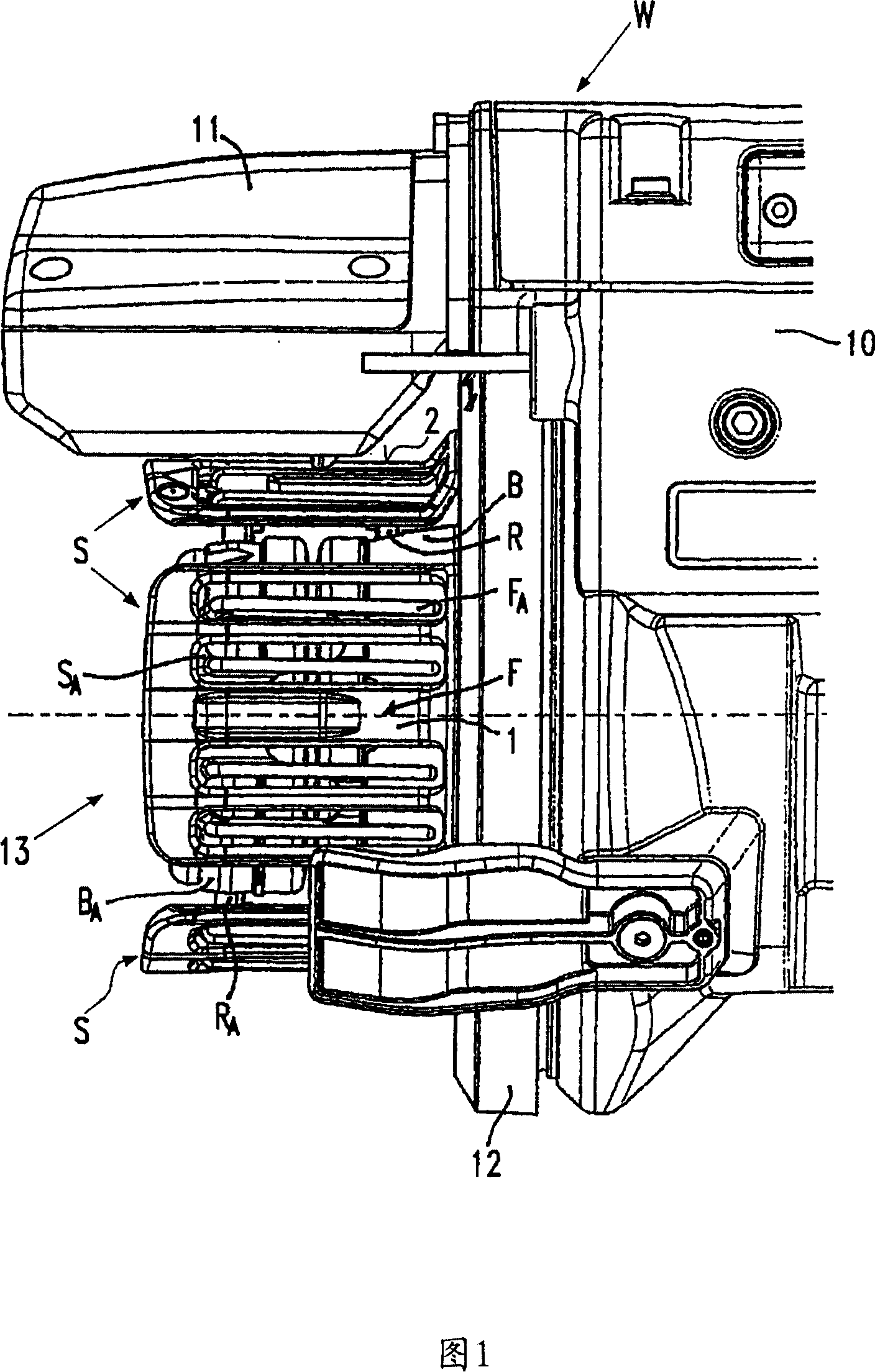
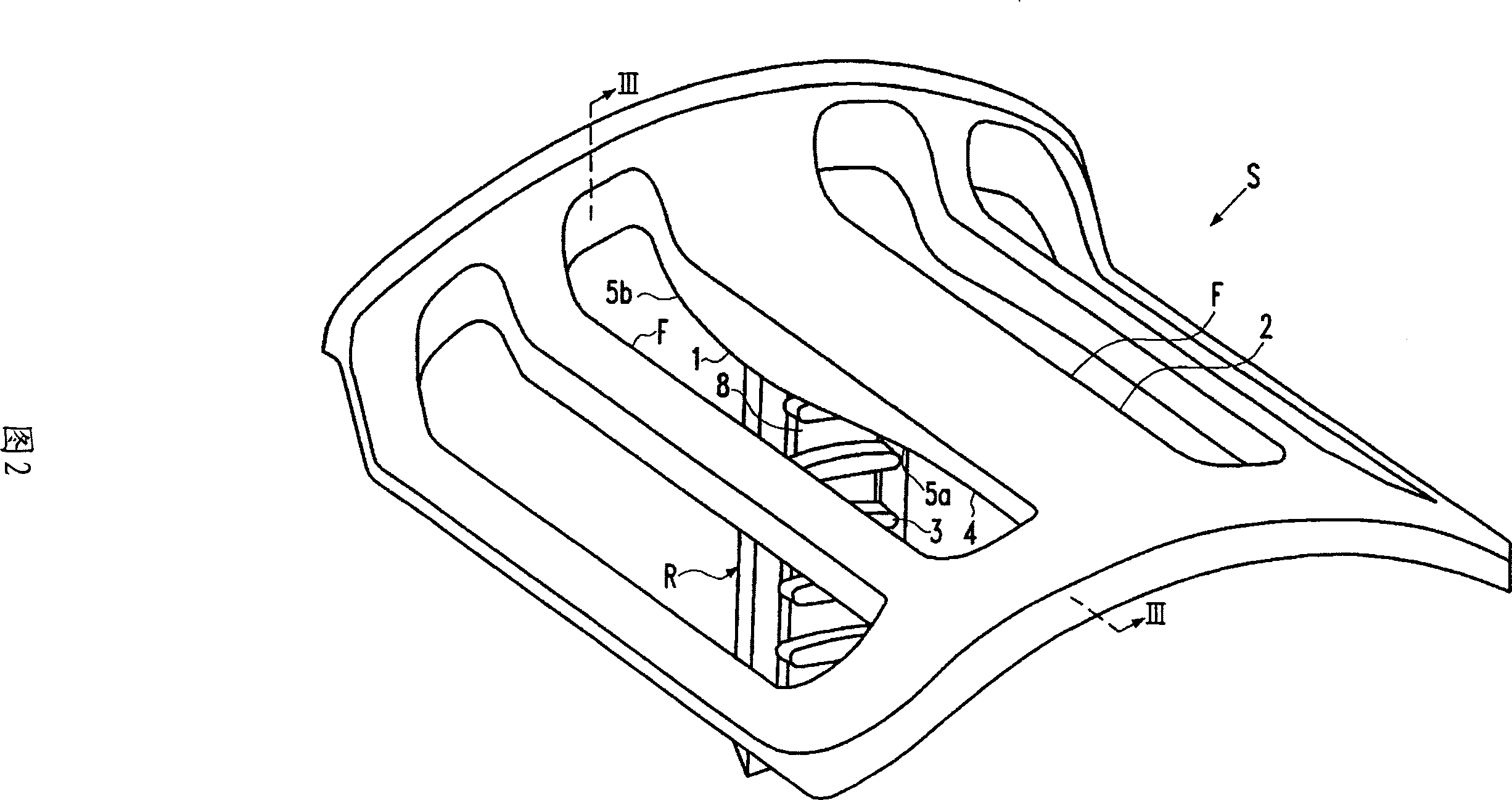
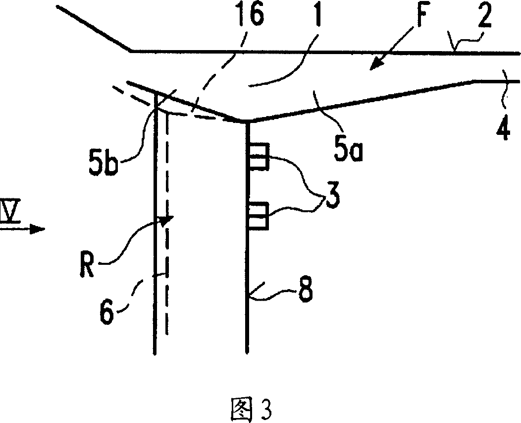
[0024] The yarn feeding device W, shown partly in FIG. 1 , is a so-called measuring yarn feeding device as conventionally applied in nozzle looms. The yarn feeding device W has a housing 10 which fixedly supports a storage body 13 . The brake housing 11 fixed to the housing 10 is structurally combined with the outer circumference of the storage body 13 in a substantially identical and regularly distributed total number in the circumferential direction of the storage body 13, for example one of the four arcuate portions S Circumferential position. Each segment S comprises several substantially parallel fingers F, each finger forming a yarn storage surface 2, and a rod R substantially perpendicular to the lower face of the central finger F. Each rod R serves to fix and radial...


PUM


Abstract

A yarn feeder (W) comprising a variable diameter stationary storage body (13) consisting of separated segments (S, SA) received in radial guidances (7) of a support structure (B), each segment comprising at least one finger (F) and a rod (R) unitarily formed with the finger (F), the rod (R) being connected to the lower side of the finger in a junction region, the rod carrying engagement elements (3) at a front side (8) and defining longitudinal guiding surfaces (G) at other sides of the rod, the junction region (1) having at least a gusset (5a) at the transition between the front side (8) and the lower side of the finger, the junction region (1), furthermore, comprising an additional gusset (5b) at a transition from the rear side of the rod into the lower side of the finger. The guiding surfaces (G)- in a crosssection of the rod (R)- being arranged pairwise and with a V-shape.

Description

technical field [0001] The invention relates to a yarn feeding device according to the preamble of claim 1 . Background technique [0002] Among the yarn feeders for looms, there are so-called measuring yarn feeders used in nozzle looms such as air-jet looms and water-jet looms. The insertion device of the nozzle loom cannot measure the correct weft yarn length for a weft yarn pick. Therefore, the measuring yarn feeding device is provided with a braking device for releasing a certain total number of yarn reels only during each pick of the weft yarn. The fabric width of the air jet loom can be changed. The diameter of the storage body can be changed to match the width of the weft thread released by the braking device during each weft thread picking of the fabric width (variable diameter storage body). The storage body of the measuring yarn feeding device usually comprises several separate segments which are supported by rods in the radial guides of the support body of the ...

Claims


Application Information

Patent Timeline
Patent Type & Authority Applications(China)
IPC IPC(8): B65H51/22D03D47/36
CPCD03D47/362
Inventor 杰拉尔多·索尔顿
Owner VANDEWIELE SWEDEN AB
Why Eureka
Try Eureka