
Yarn feeder

A kind of equipment and yarn feeding technology, which is applied in the direction of thin material processing, textile and paper making, loom, etc., can solve the problems that the joint area is easy to be damaged, and the free end part is easy to vibrate violently, so as to improve the running performance, increase the firmness, modify simple effect

Active Publication Date: 2009-12-09
VANDEWIELE SWEDEN AB
View PDF8 Cites 0 Cited by
  • Summary
  • Abstract
  • Description
  • Claims
  • Application Information

AI Technical Summary

Problems solved by technology

Due to the unavoidable vibrations during the operation of the yarn feeding device, the bonding area in each bow is prone to damage and when the diameter of the storage body is adjusted, and this diameter is larger than the minimum diameter, the free end part is prone to violent vibrations, because in After this, a substantial part of the length of the rod is no longer supported by the guides in the support

Method used


Image

  • Yarn feeder
  • Yarn feeder
  • Yarn feeder

Examples


Embodiment Construction

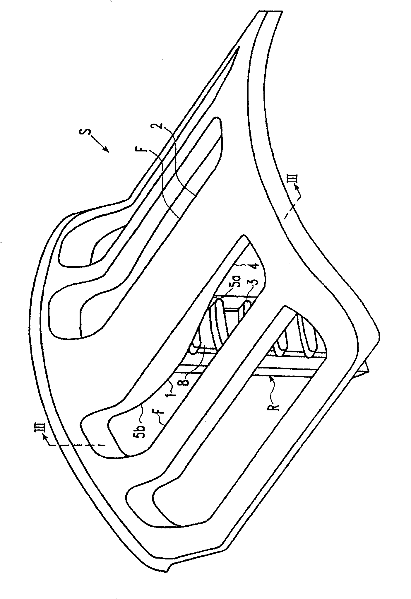
[0023] Figure 6-9 The conventional arcuate portion S'shown is designated with a dot primed reference numeral. Of the embodiments of the present invention Figure 1-5a The same reference numerals without dot primes are used in.

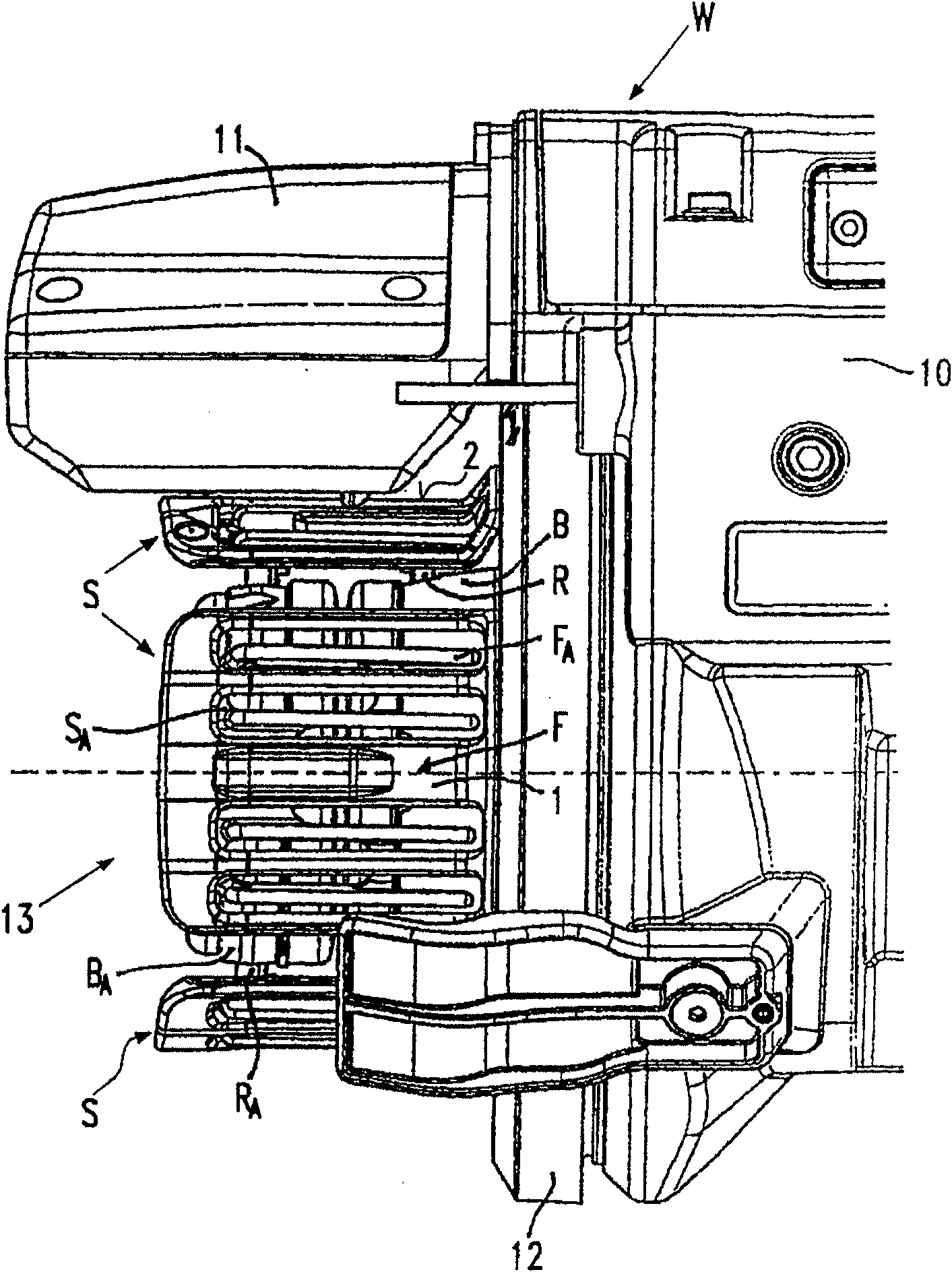
[0024] Yarn feeding equipment W, such as figure 1 As shown in part, it is a so-called measuring yarn feeding device that is conventionally used in nozzle looms. The yarn feeding device W has a housing 10 and the housing 10 fixedly supports a storage body 13. The brake housing 11 fixed to the housing 10 is structurally combined with the outer circumference of the storage body 13 in a total number that is substantially the same and regularly distributed in the circumferential direction of the storage body 13, such as one of the four fixed arches S The circumferential position. Each fixed arcuate portion S includes a number of substantially parallel finger structures F and a first rod R. Each finger structure constitutes the yarn storage surface 2, and the...


PUM


Abstract

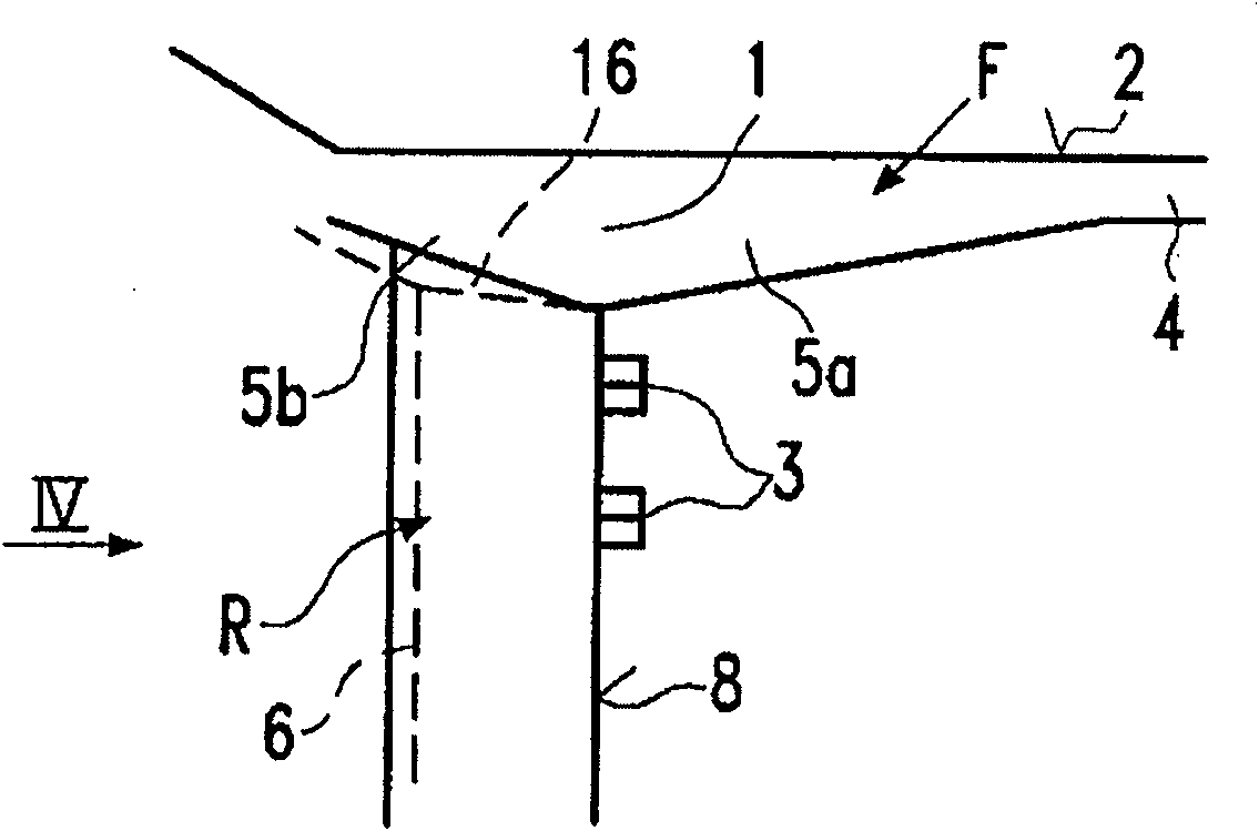
A yarn feeding device (W) comprising a fixed storage body (13) of variable diameter comprising separate fixed arcuate Section (S) and additional arcuate section (SA), each separate arcuate section includes at least one finger-like structure (F) and a first rod (R) integrally formed with the finger-like structure, in the connection area the first rod (R ) is connected to the lower face of the finger structure (F), the first rod (R) carries the coupling element (3) on the front face (8) of the first rod (R) and defines a longitudinal guide surface on the other side of the first rod (R) (G), the joint area (1) has at least one front gusset (5a) at the transition between the front surface (8) and the lower face of the fingers, and the joint area (1) includes The rear gusset (5b) at the transition from the rear surface of the to the lower face of the fingers. The guide surfaces (G) are arranged in pairs on the cross-section of the first rod (R) and have a V-shaped arrangement.

Description

Technical field [0001] The present invention relates to a yarn feeding device as follows: a yarn feeding device includes a fixed storage body with a variable diameter, the fixed storage body includes a separate fixed arcuate part and an additional arcuate part, the fixed arcuate part and the additional arcuate part Adjustably located in the radial guide portion of the support structure, each arcuate portion includes at least one finger structure and a first rod, the first rod and the finger structure are integrally formed, and the first rod is connected to the finger structure in the bonding area The lower surface of the structure is connected and extends perpendicular to the lower surface of the finger structure. The first rod carries the coupling element on the front surface and has a longitudinally extending guide surface on the other first rod surface. The coupling area includes a front surface. The front corner plate of the transition between the surface and the lower face of...

Claims


Application Information

Patent Timeline
Patent Type & Authority Patents(China)
IPC IPC(8): B65H51/22D03D47/36
CPCD03D47/362
Inventor 杰拉尔多·索尔顿
Owner VANDEWIELE SWEDEN AB
Learn More