Indexable rotary cutting tool and insert used therein

a cutting tool and indexing technology, applied in the field of indexing rotary cutting tools, can solve the problems of reducing the life of cutting edges, deteriorating finished surface quality, and cutting edges likely to slip and break, so as to improve the finished surface condition of work, improve the cutting performance of peripheral cutting edges, and improve the cutting performance. the effect of wear resistan

Active Publication Date: 2016-07-28
HITACHI TOOL ENG LTD
View PDF31 Cites 12 Cited by
  • Summary
  • Abstract
  • Description
  • Claims
  • Application Information

AI Technical Summary

Benefits of technology

[0005]Accordingly, an object of the present invention is to provide an indexable rotary cutting tool having improved breakage resistance and wear resistance in cutting edges to improve finished surface conditions of a work, and an insert used therein, particularly an insert having improved cutting performance in peripheral cutting edges while preventing chipping and breakage in bottom cutting edges, thereby improving finished surface conditions of a work.

Problems solved by technology

However, when an indexable rotary cutting tool comprising small inserts is used for accurate finishing, chipping and breakage are likely to occur in cutting edges because of insufficient rigidity to stress generated by cutting.
Chipping and breakage not only reduce the life of cutting edges, but also deteriorate finished surface quality.
Accordingly, the cutting insert 303 of JP 8-66815 A cannot improve the cutting performance of the peripheral cutting edge while preventing the chipping and breakage of the bottom cutting edge, failing to improve a finished surface condition of a work.

Method used


Image

  • Indexable rotary cutting tool and insert used therein
  • Indexable rotary cutting tool and insert used therein
  • Indexable rotary cutting tool and insert used therein

Examples


first embodiment

[0057](1) Insert

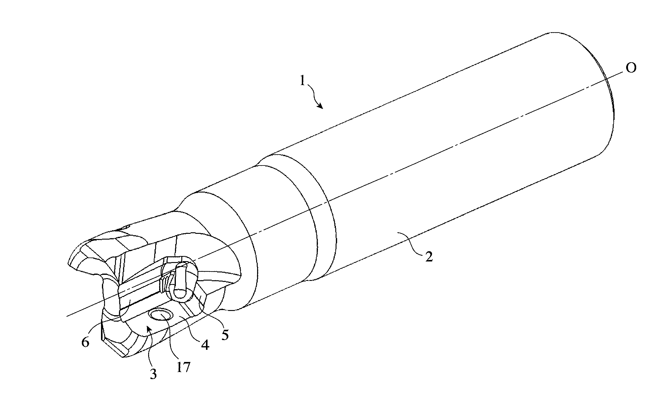
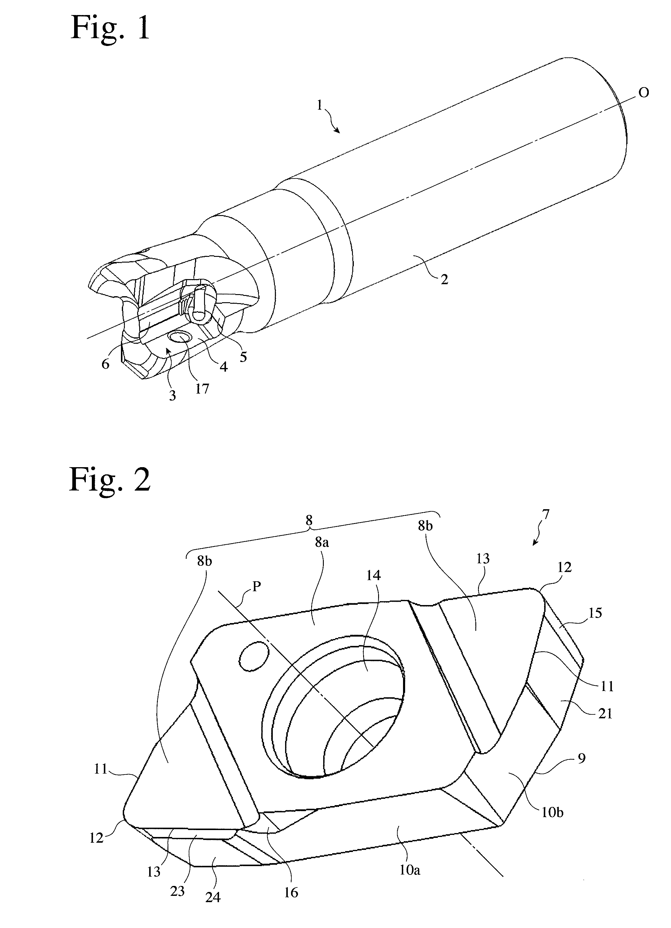
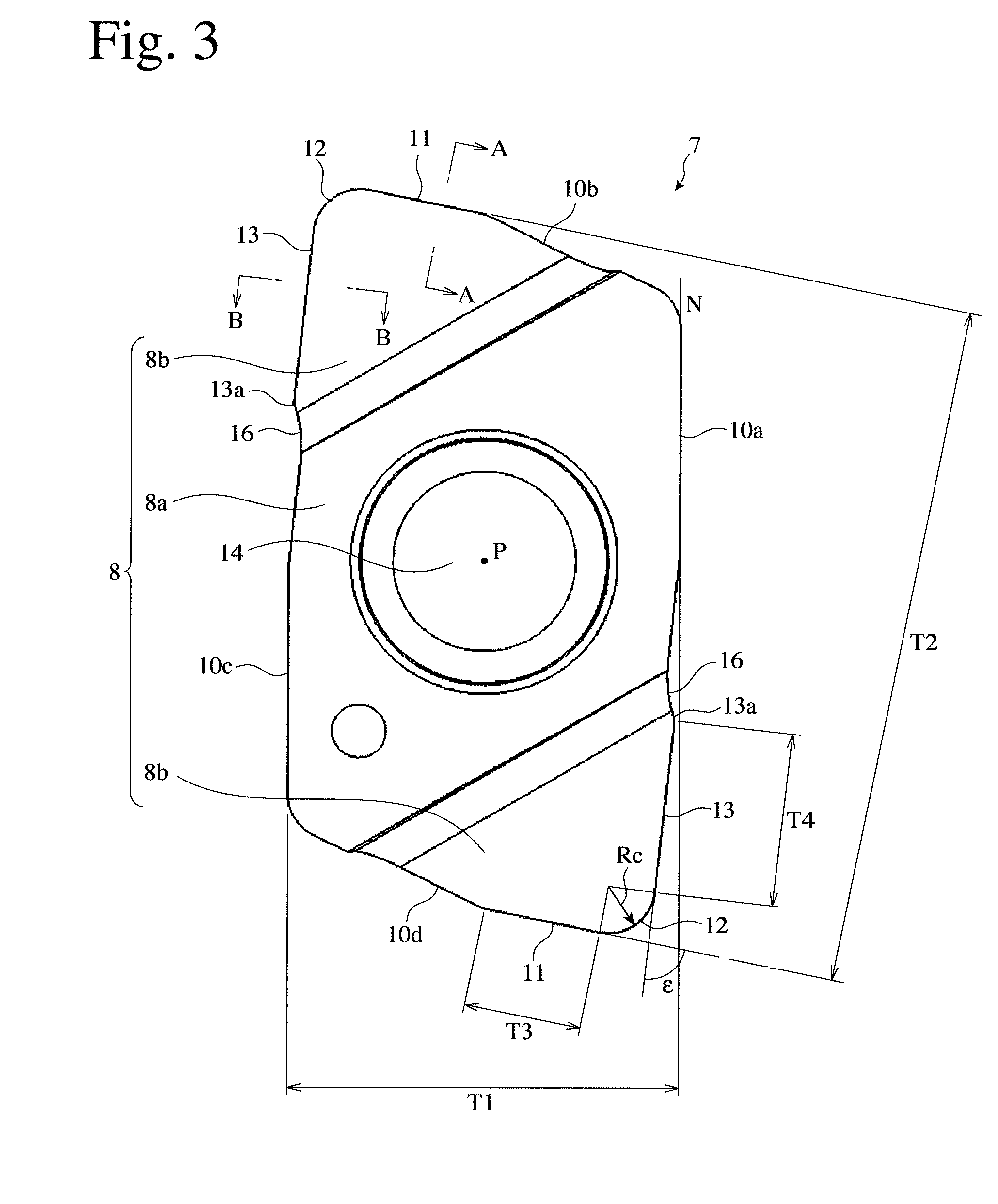
[0058]As shown in FIGS. 2-5, an insert 7 according to the first embodiment of the present invention comprises an upper surface 8 having a substantially parallelogramatic shape, a lower flat surface 9 opposing the upper surface 8, and side surfaces 10 connecting the upper surface 8 to the lower surface 9. The upper surface 8 comprises a first center upper surface region 8a, and second upper surface regions 8b on its both sides. The first upper surface region 8a has a center hole 14 penetrating from an upper surface to a lower surface for receiving a fastening screw. The insert 7 is rotationally symmetric with respect to the center axis P of the center hole 14. As shown in FIGS. 2-4, the center hole 14 is a tapered hole, whose diameter is gradually decreasing toward the lower surface 9 in a thickness direction of the insert 7. The second upper surface region 8b constitutes a common rake face of a bottom cutting edge 11, a corner cutting edge 12 and a peripheral cutting...

second embodiment

[0081]As shown in FIG. 17, an insert 7′ according to the second embodiment of the present invention does not differ from the insert 7 according to the first embodiment of the present invention, except that a bottom cutting edge 11 of the former is a wiper edge 11a perpendicular to a peripheral cutting edge 13. Accordingly, the insert 7′ in the second embodiment can be attached to the same tool holder 2 as that of the insert 7 in the first embodiment. Thus, with respect to the insert 7′ in the second embodiment and an indexable rotary cutting tool having inserts 7′ attached thereto, only those related to the wiper edge 11a will be explained below, with other portions' explanations omitted.

[0082]As shown in FIG. 17, the percentage of the length T3′ of the wiper edge 11a to the distance T1 between the long sides is preferably 8-25%, more preferably 10-24%, most preferably 12-23%. When the length T3′ of the wiper edge 11a is less than 8%, the wiper edge 11a is too short, providing low f...

third embodiment

[0084](1) Insert

[0085]As shown in FIGS. 18 and 19, an insert 107 according to the third embodiment of the present invention comprises an upper surface 108 having a substantially equilateral-triangular shape, a lower flat surface 109 opposing the upper surface 108, and side surfaces 110 connecting the upper surface 108 and the lower surface 109. The upper surface 108 comprises a first central upper surface region 108a having a substantially equilateral-triangular shape, and second upper surface regions 108b each extending from the first central upper surface region 108a and having a substantially equilateral-triangular shape.

[0086]The first upper surface region 108a has a center hole 114 for a fastening screw, which penetrates from the upper surface to the lower surface. With respect to the center axis P of the center hole 114, the insert 107 has rotational symmetry. The center hole 114 is a tapered hole having a diameter gradually decreasing toward the lower surface 109 in a thickne...


PUM


Abstract

An insert detachably attached to an indexable rotary cutting tool, comprising an upper surface having cutting edges along the ridgeline, a lower surface, side surfaces, and a center hole for a fastening screw; each cutting edge comprising a corner cutting edge formed in each acute corner portion, and a bottom cutting edge and a peripheral cutting edge formed along the ridgelines on both sides of the corner cutting edge; the bottom cutting edge and the peripheral cutting edge having different clearance angles; a flank of the corner cutting edge comprising an angle-changing surface portion having a clearance angle continuously changing in a region from the bottom cutting edge to the peripheral cutting edge; and the length of the peripheral cutting edge being restricted by a receding portion adjacent to an upper end of the peripheral cutting edge.

Description

FIELD OF THE INVENTION[0001]The present invention relates to an indexable rotary cutting tool capable of cutting a work with a good finished surface condition, and an insert used therein.BACKGROUND OF THE INVENTION[0002]An indexable rotary cutting tool having pluralities of inserts each having cutting edges detachably attached to a tool holder can cut a work with high efficiency. However, when an indexable rotary cutting tool comprising small inserts is used for accurate finishing, chipping and breakage are likely to occur in cutting edges because of insufficient rigidity to stress generated by cutting. Chipping and breakage not only reduce the life of cutting edges, but also deteriorate finished surface quality. Accordingly, various inserts having such shapes as to avoid the chipping and breakage of cutting edges have been proposed.[0003]One means for preventing chipping and breakage is to reduce the vibration of cutting edges. An insert for a cutting tool using such means is discl...

Claims


Application Information

Patent Timeline
Patent Type & Authority Applications(United States)
IPC IPC(8): B23C5/20B23C5/10
CPCB23C2200/0477B23C2200/243B23C2200/286B23C2200/0433B23C5/207B23C5/109B23C2200/085B23C2200/283B23C2200/086B23C2200/125B23C5/202
Inventor MURA, HISANORIHIBATA, TADAHIROMURATA, TOMOHIRO
Owner HITACHI TOOL ENG LTD
Why Eureka
Try Eureka