Heat exchanger in particular for exhaust coolers on internal combustion engines

A technology of exhaust gas cooler and heat exchanger, which is applied in the direction of internal combustion piston engine, combustion engine, machine/engine, etc., can solve the problem of flow leakage and achieve the effect of thermal expansion

Inactive Publication Date: 2007-04-18
贝洱公司
View PDF0 Cites 1 Cited by
  • Summary
  • Abstract
  • Description
  • Claims
  • Application Information

AI Technical Summary

Problems solved by technology

[0005] A frequent problem in such partitions is flow leakage, which occurs in the area of ​​t

Method used


Image

  • Heat exchanger in particular for exhaust coolers on internal combustion engines
  • Heat exchanger in particular for exhaust coolers on internal combustion engines
  • Heat exchanger in particular for exhaust coolers on internal combustion engines

Examples


Embodiment Construction

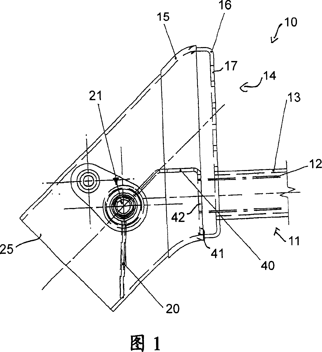
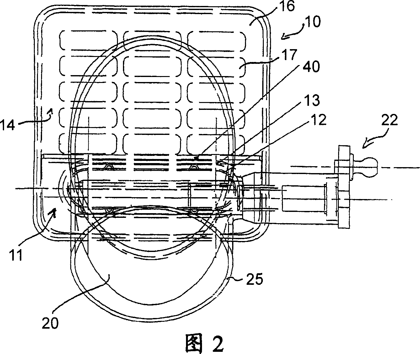
[0023] Figures 1 and 2 show longitudinal and transverse cross-sectional views of the heat exchanger 10 guided by the flow of the carrier medium in the inflow region. The heat exchanger 10 is designed as a double-pipe type, wherein one of the two pipes forms a bypass pipe 11 and the other pipe forms a heat exchange pipe 14. The heat exchange pipe 14 is designed to realize energy exchange between the heat exchange medium (which exchanges energy to the carrier medium) formed in the area of ​​the carrier medium and the heat exchange pipe 14, and thereby realize the heating or cooling of the carrier medium. In the illustrated embodiment, the heat exchanger is used in an exhaust gas cooler of an internal combustion engine, in which the carrier medium is formed by the exhaust gas flow and is accordingly supplied with cooling water as a heat exchange medium. The heat of the carrier medium—the exhaust gas is transferred to the heat exchange medium—water, and reduces the temperature of the ...


PUM


Abstract

The invention relates to a heat exchanger (10), in particular for an exhaust gas cooler of an internal combustion engine. The object of the invention is to achieve a separation of the carrier medium into two partial flows as free as possible of flow leakage by means of a suitable design of the partition ( 40 ). A heat exchanger (10) which can be used as an exhaust gas cooler of an internal combustion engine has a heat exchange line (14) and a bypass line (11), wherein in the flow line (25) the A switching valve (20) is provided upstream, which separates the carrier medium flowing into the heat exchange line and the bypass line. In order to maintain separation between the partial flow through the bypass line (11) and the partial flow through the heat exchange line (14), a partition (40) is provided which, according to the invention, extends from the switching valve (20) to the beginning of the bypass pipe (11).

Description

Technical field [0001] The present invention relates to a heat exchanger, which is particularly used in an exhaust gas cooler of an internal combustion engine. Background technique [0002] Heat exchangers used in many applications are well known. In addition, an arrangement of a so-called bypass duct is also known, which guides the carrier medium flowing through the heat exchanger from the side on the heat exchanger body. In addition, the carrier medium flows through the heat exchanger. When the carrier medium flows in the heat exchange area and transfers energy to the heat exchange medium or transfers energy from the heat exchange medium to the carrier medium, the heat exchange medium does not generate substantial energy with the carrier medium. exchange. [0003] In order to adjust or control the temperature generated by the carrier medium downstream of the heat exchanger, it is well known to install a switching valve in the flow pipe leading to the heat exchanger upstream of ...

Claims


Application Information

Patent Timeline
IPC IPC(8): F01N3/04
CPCY02T10/16Y02T10/121
Inventor 克劳斯·贝克赫维·帕朗雄马丁·申德勒
Owner 贝洱公司
Why Eureka
Try Eureka