
Heating cooking apparatus

A technology for cooking appliances and heating components, which is applied to induction heating, induction heating devices, stove/stove tops, etc., can solve the problems of narrow viewing angle, difficult to see the display state, inconvenient viewing, etc., and achieves wide viewing angle and humanistic design concept. optimized, easy-to-see display

Active Publication Date: 2012-09-05
IRIS OHYAMA
View PDF2 Cites 0 Cited by
  • Summary
  • Abstract
  • Description
  • Claims
  • Application Information

AI Technical Summary

Problems solved by technology

However, since the liquid crystal display is illuminated by the backlight, the viewing angle (the angle at which the display can be seen) is narrow, and it is difficult to see the display state from an oblique direction.
In addition, the liquid crystal display not only has a display state, but also has a non-display state part, so there is also the problem of inconvenient viewing.

Method used


Image

  • Heating cooking apparatus
  • Heating cooking apparatus
  • Heating cooking apparatus

Examples


Embodiment Construction

[0022] Hereinafter, embodiments of the present invention will be described in detail with reference to the drawings.

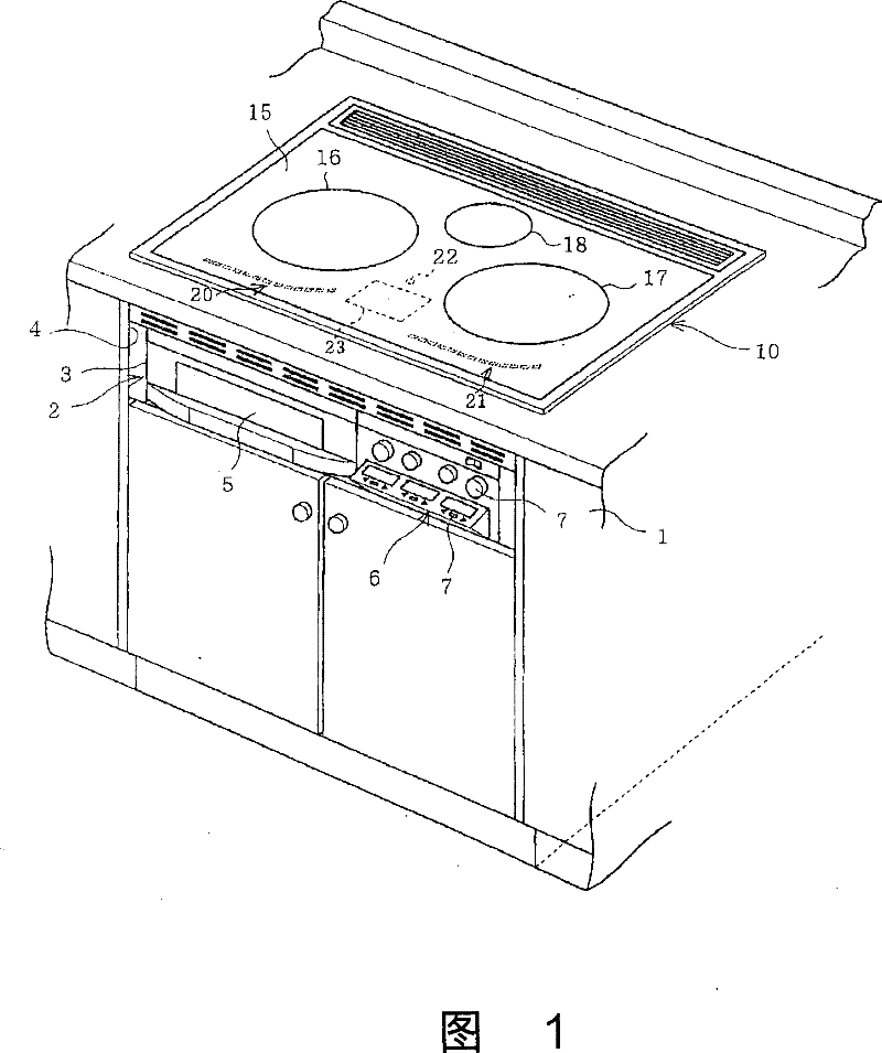
[0023] Figure 1 to Figure 5 Example 1 of the present invention is shown. first, figure 1 It is an external perspective view showing a state in which a heating cooker 2 is installed in a kitchen cabinet 1 . Should figure 1 Among them, the main body 3 of the heating cooker 2 is stored in the storage part 4 provided in the cabinet 1 . An oven 5 is arranged on the left side of the main body 3, and an operation part 6 is arranged on the right side. A plurality of switches are provided on the operation unit 6 .

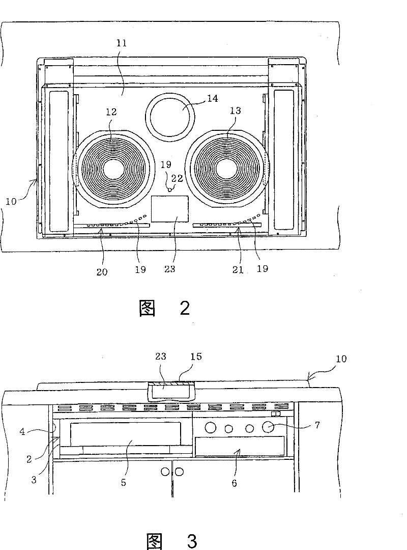
[0024] In the upper part of the main body 3, such as figure 2 As shown, an upper heating unit 10 is provided. In this upper heating unit 10, a left heating coil 12 and a right heating coil 13 for induction heating are respectively arranged on the left and right sides in a rectangular box-shaped upper casing 11 with an open upper surface. The centr...


PUM


Abstract

A heating cooking apparatus formed to heat a heated material placed on a top plate (15) by heating means (12), (13), and (14) installed under the top plate (15). The top plate (15) is formed semi-transparent, and a fluorescent character display tube (23) is installed under the top plate (15).

Description

technical field [0001] The present invention relates to a heating cooker configured to heat an object to be heated placed on a top plate by using a heating member arranged under the top plate. Background technique [0002] This heating cooker is known to have its structure to make, and for example as induction heating cooker, liquid crystal display is set under the top plate, also backlight is set at the back side of this liquid crystal display simultaneously, utilizes this liquid crystal display to display as heating element. The energization / de-energization of the heating coil, the degree of input electric power, etc. (for example, refer to Patent Documents 1 and 2). In the case of such a configuration, the portion corresponding to the liquid crystal display on the top plate is transparent, and the display of the liquid crystal display can be seen from above the top plate. [0003] Patent Document 1: Japanese Patent Application Laid-Open No. 7-94267 [0004] Patent Docum...

Claims


Application Information

Patent Timeline
Patent Type & Authority Patents(China)
IPC IPC(8): H05B6/12F24C15/10
Inventor 今本和成江碕猛近藤正夫松尾胜春
Owner IRIS OHYAMA
Learn More